Why and How to Sinusoidally Control Three-Phase Brushless DC Motors
資料提供者:DigiKey 北美編輯群
2017-01-17
The brushless DC (BLDC) motor has found favor in applications as diverse as computer cooling fans, disk drives, cordless power tools, electric bicycles, and record turntables. As prices continue to fall, the motors will find even wider use in all but the most price-sensitive applications. However, as demand increases, so too does the requirement for smoother, more efficient, and quieter BLDC motor operation.
While sinusoidal control is the best way to achieve these goals, it comes with extra cost and complexity relative to more traditional, trapezoidal control techniques. This article will discuss BLDC motor control basics and the reasons to consider sinusoidal control over trapezoidal. It will then introduce some commercial-off-the-shelf solutions in the form of integrated motor driver and controller chips which can be used to make the transition to sinusoidal less daunting and accelerate the design process.
BLDC motor basics
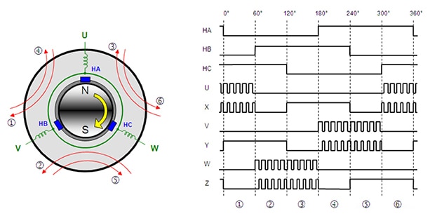
A BLDC motor overcomes the requirement for a mechanical commutator by reversing the motor set-up; the windings become the stator and the permanent magnets become part of the rotor. Typically powered by a six-MOSFET bridge controlled using pulse-width modulation (PWM), the windings are commutated in a controlled sequence to produce a rotating magnetic field that “drags” the rotor around and drives an attached load (Figure 1).

Figure 1: BLDC motors are powered by sequentially energizing the windings using a PWM signal. The duty cycle of the PWM signal is proportional to the drive voltage. In this image, “U”, “V” and “W” are the windings and “HA”, “HB” and “HC” are the position-sensing Hall-effect sensors. (Image source: ON Semiconductor/Fairchild)
The sequence is determined by the relative positions of stator and rotor, as measured by either Hall-effect sensors or the magnitude of the back electromagnetic force (EMF) generated as the motor rotates (in a “sensorless” unit).
There are three control schemes for electronic commutation: trapezoidal, sinusoidal and field oriented control (FOC). FOC is expensive to implement and is reserved for high-end applications and is not discussed in this article.
For many applications, the trapezoidal controlled BLDC motor is the best solution. They are compact, reliable and are rapidly falling in price, making them particularly suitable for many small motor applications including automotive, white goods, and computers.
Additionally, the trapezoidal technique is the easiest to implement and is the most popular. Each phase of the motor is powered by direct current which is commutated every 60˚. The phase is either driven “high”, “low”, or is left floating.
In theory, such a system can generate a smooth, constant torque. In practice, it’s impossible for the current of a given phase to instantaneously change from low to high. Instead, the resulting rise time generates a ripple in the output that coincides with the commutation timing (Figure 2).

Figure 2: Electrical waveform for a three-phase BLDC motor using trapezoidal control. Note the slight dip in each phase’s drive current as commutation occurs. This causes a ripple in the motor’s torque. The dotted lines trace the trapezoidal profile of the back EMF in each phase with zero-crossing points coinciding with the midpoint of the phase’s float cycle. (Image source: Texas Instruments)
Torque ripple is not the only drawback with trapezoidal-controlled BLDC motors. Another disadvantage is electrical and acoustic noise. A key source of this noise is the rapidly switching DC powering the individual phases. From an electrical perspective, this noise heats up the windings and reduces efficiency. From an acoustic perspective, the “buzz” generated by the switching frequency and its harmonics is at an audible frequency that while not necessarily loud, can be grating.
(For more information on BLDC motor operation and trapezoidal control schemes, refer to the library article, “How to Power and Control Brushless DC Motors”.)
Implementing sinusoidal control
Sinusoidal control is complex and very few engineers can implement a system from first principles. A better approach is to embrace the knowledge of a silicon vendor and work with a BLDC motor design development kit. An example is NXP's FRDM-KE04Z.
This uses the Kinetis KE04 ARM® Cortex®-M0 MCU to run the sinusoidal algorithms. Implementation is further eased by basing the control-circuit design on one of a wide range of BLDC driver chips. These devices typically integrate PWM control and power electronics into a single chip and provide an interface to an external MCU. Other devices integrate the MCU and require just a few additional passive components to form a complete circuit.
Sinusoidal alternative: the “saddle” profile
Pure sinusoidal drive voltages are rarely used in practice because they are inefficient to generate for each motor terminal with respect to ground. A better method is to generate sinusoidal differential voltages between phases, shifted by 120˚ for commutation. This is done by varying the PWM duty cycle (and hence drive voltages) relative to ground using a “saddle” profile, rather than sinusoidal (Figure 3). The resulting phase current driving the motor then follows the pure sine-wave variation of the phase-to-phase voltage.

Figure 3: Practical sinusoidal control implementations don’t drive each phase with a pure sine-wave voltage. Instead a saddle-shaped voltage is applied which results in a sine-wave differential voltage between two terminals, phase-shifted by 120˚ for commutation. The result is higher torque and speed for a given voltage and improved efficiency. (Image source: NXP)
The saddle profile technique offers two advantages: First, the maximum differential voltage generated is higher than can be produced with a pure sinusoidal signal, offering higher torque and speed for a given input. Second, each terminal output is zero for 1/3 of the time, further reducing switching losses in the power stage.
One of the complexities of the sinusoidal control approach is the precise control of duty cycle against motor angle demanded to form the saddle-shaped voltage input. This becomes even more difficult at high revolutions. A major part of the challenge is that the motor position is only accurately determined six times per revolution while one of the rotor’s magnet poles passes one of the three Hall sensors. A typical solution, and the one employed by the FRDM-KE04Z for example, is to estimate the motor angle (“mtrAngle”) between the Hall sensors by multiplying the rotor’s angular velocity by ∂T and assuming the motor speed is constant.
A look-up table is then used to determine PWM duty cycle for a given angle. In the FRDM-KE04Z, the look-up table offers a duty cycle for each degree (actually 384 increments) of motor rotation.
Here is a code snippet which illustrates how the FRDM-KE04Z computes the angle (for clockwise rotation)1:
Copy
deltaAngle = F32Add(deltaAngle,F32Abs(velocityAct));

if (deltaAngle >= DELTANGLE_MAX) //limit deltaAngle range into
{                                     [0,64]
deltaAngle = DELTANGLE_MAX;
}
mtrAngle = HallTableCW[motorPosition];
mtrAngle += (tU16)((deltaAngle) >> 12);
mtrAngle += (tU16)advanceAngle;
if (mtrAngle >= 384)
       {
           mtrAngle -= 384;
       }
After the motor angle is calculated, the duty cycles can be calculated by using the codes below which access the look-up table:
Copy
dutyCycleU16A = (Frac16)(((Frac16)dutyCycleU16 * (Frac16)SinusoidalWaveTable[mtrAngle]) >> 8);
      if (mtrAngle < 128)
       {
dutyCycleU16B = (Frac16)(((Frac16)dutyCycleU16 * (Frac16)SinusoidalWaveTable[mtrAngle + 256]) >> 8);
}
else
{
dutyCycleU16B = (Frac16)(((Frac16)dutyCycleU16 * (Frac16)SinusoidalWaveTable[mtrAngle - 128]) >> 8);
   }
if (mtrAngle >= 256)
{
dutyCycleU16C = (Frac16)(((Frac16)dutyCycleU16 * (Frac16)SinusoidalWaveTable[mtrAngle -256]) >> 8);
}
else
{
dutyCycleU16C = (Frac16)(((Frac16)dutyCycleU16 * (Frac16)SinusoidalWaveTable[mtrAngle + 128]) >> 8);
}
Code Listing: Code required to calculate the motor angle and PWM duty cycle for the FRDM-KE04Z development kit. (Code source: NXP)
Such a method takes advantage of a side effect of using the saddle-shaped profile. Specifically: because the voltage value for a given phase is zero for a third of the time, no look-up is required for that period, demanding fewer processor resources and allowing the use of a more modest, lower-cost MCU for the application.
A drawback of the method is that the interpolation of motor speed between Hall sensors is likely to be inaccurate during the start-up phase when the motor is accelerating quickly. This can cause a jerky torque response.
One popular solution to this problem, implemented in ROHM Semiconductor's BD62011FS fan motor controller, is to start the motor in a trapezoidal control mode and switch to sinusoidal control once it reaches a given speed (typically 5 - 100 Hz), when the interpolation is likely to be more accurate.
Rohm’s device is aimed at control of BLDC motors equipped with Hall sensors. The chip features PWM control of both high- and low-side MOSFETs and sinusoidal commutation logic. It can operate from a 10 to 18 V input and provide between 2.1 and 5.4 V (up to 1 W) at the output. Target applications are air conditioners, water pumps and white goods.
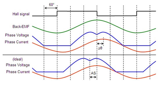
Another design challenge is the phase lag between the drive voltage and the resultant sine-wave current for a given phase that naturally occurs in an uncompensated BLDC motor. The motor will operate satisfactorily, but efficiency will be reduced, defeating much of the purpose of implementing a sinusoidal control scheme in the first place. The source of this inefficiency is not the phase lag between drive voltage and phase current, rather the phase lag between phase current and the sinusoidal back EMF.
Fortunately, many drive chips, including the LV8811G power MOSFET driver from ON Semiconductor, allow the designer to introduce a phase-angle advance to the sinusoidal drive current to ensure its peak coincides with that of the back EMF. The phase-angle advance is typically set to increase linearly with the input voltage, which determines the motor’s speed (Figure 4).

Figure 4: In an uncompensated sinusoidally-controlled BLDC motor, phase current lags back EMF causing inefficiencies (top). Many driver chips include phase-angle advance, which allows the designer to phase current so it coincides with back EMF (bottom). (Image source: ON Semiconductor/Fairchild)
The LV8811G is a three-phase BLDC motor driver controlled by a single Hall sensor and adopting sinusoidal control. Either a direct PWM pulse input or a DC voltage input can be chosen to control the motor’s rotary speed.
When using the LV118811G, the designer can set the initial conditions for the speed at which the phase angle starts to advance and the gradient of the phase angle advance slope via resistor dividers on pins PH1 and PH2. The chip’s internal logic then determines the phase angle advance for a given speed based on a predetermined formula.
Sensorless BLDC sinusoidal control
Sinusoidal control can also be implemented with sensorless BLDC motors. The operation of these motors is identical to the versions that use Hall-effect sensors except that positional information is obtained by measuring the back EMF. (For more information, see the library article “Controlling Sensorless, BLDC Motors via Back EMF”.)
Texas Instruments' DRV10983, for example, is designed for sinusoidal control of sensorless BLDC motors. The chip integrates the power electronics, can be interfaced with an external MCU and can provide continuous drive current up to 2 A. Sinusoidal control is achieved using the company’s proprietary control scheme.
In this scheme, the commutation control algorithm continuously measures the motor phase current and periodically measures the supply voltage. The device then uses this information to calculate back EMF and then motor position. Motor speed is determined by the number of zero crossings of one phase’s back EMF in a unit time. The chip also allows for phase-angle advance to align phase current with back EMF for maximum efficiency.
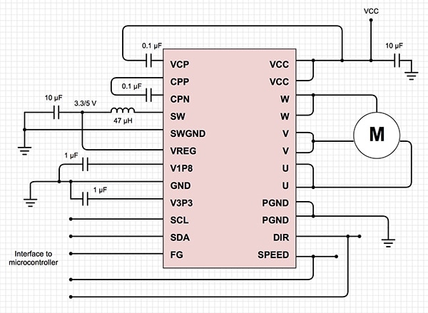
The DRV10983 is specifically designed for cost-sensitive, low-noise, low external component count applications (Figure 5).

Figure 5: Texas Instruments’ DRV10983 enables a designer to build a sinusoidally-controlled BLDC motor system with an inexpensive MCU and a small selection of passive components. (Diagram drawn using DigiKey Scheme-it® from an original source image from Texas Instruments)
Conclusion
BLDC motors are proving a popular alternative to conventional brushed types because of their performance and reliability advantages. For many applications, trapezoidal control is satisfactory, but if the designer is tasked with enhancing efficiency, reducing electrical and acoustic noise and improving torque delivery, sinusoidal control should be considered.
While sinusoidal control adds complexity and cost, development tools, capable MCUs and integrated driver ICs have considerably eased the design process, making sinusoidal control more practical and less daunting. Better yet, the development tools’ flexibility and driver ICs’ adaptability allow designers to fine tune the motor for their application, and focus more on product differentiation.
References:
- “Sinusoidal Control of BLDCM with Hall Sensors Based on FRDM-KE04Z and Tower Board,” Liu Zhen, Freescale Semiconductor Application Note (AN4869), March 2014.
- “Development of Sinusoidal BLDC Drive with Hall Sensors,” Joon Sung Parka et al, Korea Electronics Technology Institute, 2016.

聲明:各作者及/或論壇參與者於本網站所發表之意見、理念和觀點,概不反映 DigiKey 的意見、理念和觀點,亦非 DigiKey 的正式原則。


