Use Arduino’s Processor Flexibility for Broader Evaluation Capabilities
資料提供者:DigiKey 北美編輯群
2016-07-20
While early iterations of Arduino base board designs leveraged only Atmel 8-, 16- and 32-bit AVR microcontrollers, a number of base boards containing non-Atmel MCUs and MPUs have recently appeared. This gives designers greater flexibility, not only with respect to processor and I/O, but also provides more options with respect to taking Arduino boards beyond development, all the way through to production systems, after giving due consideration to some serious design tradeoffs.
These myriad new Arduino base boards also, of course, provide enhanced system processor flexibility in a common industry-standard and open-source hardware approach. These attributes make Arduino an appealing option for processor evaluation and selection, after which point a transition to a processor vendor-development board (along with associated software and other resources) may be appropriate. In some scenarios, however, Arduino boards may remain relevant not only through development but, in combination with the flexible enhancement capabilities delivered by "shield" expansion boards, all the way through production.
This article will showcase several example Arduino base board and shield offerings, discussing (among other things) their processor foundations and peripheral allocations. It will conclude with some suggestions for easily and effectively evaluating the processor alternatives they contain for potential use in your next design(s).
Defining Arduino
The terms "evaluation board" and "development board" are often used interchangeably, but incorrectly so. A development board, as its name implies, is intended to assist with the coding of the software that runs on the system hardware design, as well as with the connectivity between the hardware on the board and other necessary system circuitry. As such, development boards offer abundant test points and interface options, along with robust bundled software toolsets.
Inherent in the development boards' comprehensiveness (and associated high price points), however, is the implied presumption that you’re past the architecture and product proliferation evaluation stages and have already selected a particular hardware product mix. That said, some of the development board's on-board circuitry may be beyond what (or at least different than) what you intend to include in your end design. Also, a development board’s flexibility also necessitates a larger board form factor than your design's needs might dictate. More generally, the comprehensiveness of development boards' hardware and software allotments, coupled with their low shipment volumes, means that they're likely price-unpalatable for use in even low-volume, high-profit-margin system-production scenarios.
The Arduino base and expansion board specifications have rapidly become de facto industry standards over the past decade, for good reasons. Instead of attempting to provide an all-in-one unified board design, they instead leverage more elementary "base" boards. Arduino's flexible enhancement capabilities are delivered by expansion boards known as "shields", which interface to the base board over standardized connectors. The shields can be stacked, and can even be supplemented by do-it-yourself shield designs. Since numerous suppliers offer shields containing a diversity of circuits, you can easily evaluate not only different functions but also different hardware options for implementing those functions.
Similarly, where initial iterations of Arduino base board designs leveraged only Atmel AVR microcontrollers, additional base board candidates containing non-Atmel MCUs and MPUs have recently appeared, giving enhanced system processor evaluation flexibility. Additionally, Arduino's compact form factor, combined with its high-volume popularity, lead to cost-effective pricing that make it appealing not only for evaluation and subsequent development stages, but also for many modest production implementations.
Adafruit Industries DigiKey Metro Board
Let's begin with a relatively conventional base board design, Adafruit Industries DigiKey Metro Board. This derivative of the Arduino UNO R3 reference design is further DigiKey-customized beyond the foundation "Metro 328 with Headers" board via two cosmetic enhancements (the two boards are identical from a hardware standpoint):
- Its red color, versus black for the mainstream Adafruit product, along with
- A complete parts list screen printed on the board underside (Figure 1)
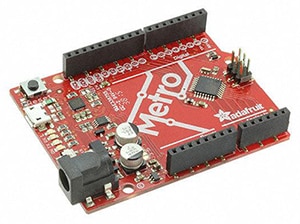
Figure 1a

Figure 1b
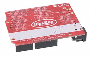
Figure 1c
Figure 1: The Adafruit DigiKey Metro board (a) is a variant of the manufacturer's mainstream Metro 328 with Headers board (b), cosmetics-customized by virtue of its red color and the complete parts list screen-printed on its underside (c).
The Atmel ATmega328P microcontroller, upon which the DigiKey Metro Board is based, is an 8-bit 20 MHz AVR RISC-based processor, with an additional 32 KBytes of in-system-programmable flash memory, 1,024 bytes of EEPROM, and 2 KBytes of SRAM. Also included with the ATmega328P are a variety of on-chip peripherals; connectivity options include 23 GPIOs, 16 touch interface channels, 24 external interrupts, a byte-oriented two-wire serial interface, and a SPI serial port.
Seeed Technology Intel Edison for Arduino Kit
On the other end of the performance spectrum is Seeed Technology's Intel Edison for Arduino Kit, one of several available hardware expansion options for the foundation Intel Edison Development Platform (Figure 2). This base board measures 127 mm x 72 mm so is quite a bit bigger than the previously mentioned 71 mm x 53 mm Arduino UNO form factor, but Arduino "shield" expansion bus standardization is maintained via the four on-board connectors. Also included on the Arduino kit is an SD card connector, along with both micro and standard-sized USB host connectors.

Figure 2a
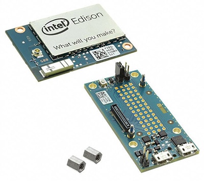
Figure 2b
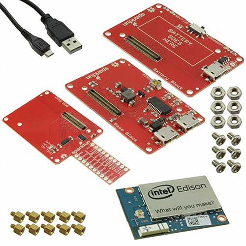
Figure 2c
Figure 2: Seeed Technology's Arduino Kit brings "shield" expansion board ecosystem support to the otherwise proprietary Intel Edison Development Platform board design (a). If "breakout" connectivity is all you require and a smaller board form factor is more to your liking, consider the company's alternative Intel Edison Breakout Kit (b). Also, SparkFun Electronics' Open Power Starter Kit provides an intermediary approach; in-between the two other boards in size, with expansion via a proprietary (albeit open source) "block" stacking scheme (c).
Intel's Edison, a relative newcomer to IoT and other embedded electronics markets, is a 22 nm-fabricated SoC with the company's 32-bit Quark microcontroller (in this particular case running at 100 MHz) at its core. Alongside it on the same chip is a dual-core, dual-threaded 500 MHz "Silvermont" Intel Atom processor array. Also included on the Intel Edison Development Platform module are 1 GByte of LPDDR3 SDRAM, 4 GBytes of EMMC-based flash memory, a USB 2.0 PHY, and both dual-band Wi-Fi and Bluetooth wireless transceivers.
For more modest-function Intel Edison evaluation development needs, with a consequent notable decrease in form-factor dimensions, Seeed also offers the Breakout Kit. Additionally, as an intermediary alternative hardware approach, Intel Edison advocates should also consider SparkFun Electronics' base board and line of expansion blocks, several of which are bundled in the company's Open Power Starter Kit. SparkFun's Intel Edison-based product line, which at the moment is sole-sourced from a vendor standpoint, albeit open source from a board design documentation standpoint, will be discussed in greater detail in an upcoming article.
UDOO Neo development boards
If Arduino's standardization is appealing but NXP’s i.MX 6 processors are more to your liking, you might want to consider UDOO's Neo development board line (Figure 3 and Table 1). Neo comes in three variants, all based on the i.MX6 SoloX SoC, and all in a 89 mm x 59 mm form factor that's in-between the dimensions of the two previously discussed options (but again with a pinout- and layout-standard set of Arduino "shield" connectors on-board).

Figure 3a
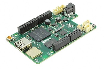
Figure 3b

Figure 3c
Figure 3: UDOO's Neo product line comes in three flavors, Basic (a), Extended (b) and Full (c), with a mix of wireless and wired network connectivity options, along with varying system memory allocations and optional motion sensors.
|
UDOO Board |
DRAM |
Wired Network Connectivity |
Wireless Network Connectivity |
On-board Motion Sensors |
|
Basic |
512 MBytes |
10/100 Mbps Ethernet |
None |
No |
|
Extended |
1 GByte |
None |
2.4 GHz-only 802.11b/g/n, Bluetooth 4 |
Accelerometer, magnetometer, and gyroscope (all 3-axis) |
|
Full |
1 GByte |
10/100 Mbps Ethernet |
2.4 GHz-only 802.11b/g/n, Bluetooth 4 |
Accelerometer, magnetometer, and gyroscope (all 3-axis) |
Table 1: UDOO Neo system board variants and options.
All three variants share the following features:
- Video in: analog (NTSC and PAL), and 8-bit parallel digital
- Video out: Micro HDMI, and LVDS + touch (I2C)
- Storage: 8-bit microSD card (with SDIO support)
- Audio: HDMI (output), S/PDIF, I2S
- USB: One USB 2.0 Type A, one microUSB (w/OTG support)
The NXP i.MX 6SoloX applications processor on which the UDOO Neo line is based comprises an ARM® Cortex®-A9 processor core (running up to 1 GHz) alongside an ARM Cortex-M4 core (up to 200 MHz). Also integrated is a Vivante GC400T 2D/3D graphics accelerator.
Analog Devices ADUCM360 base board
If ARM's Cortex-M series of cores is your sole processor focus, you should check out Analog Devices ADUCM360 base board, which the manufacturer notes is form-factor compatible with the 101.6 mm x 53.3 mm Arduino Due reference board design (Figure 4). The ADuCM360 application processor on which the board is based represents a 3.9 Ksamples/s, 24-bit data acquisition system, incorporating dual 24-bit multichannel sigma-delta ADCs, a 32-bit ARM Cortex-M3 processor core delivering up to 20 MIPS peak performance, and 128 KBytes of EEPROM-based flash memory along with 8 KBytes of SRAM.
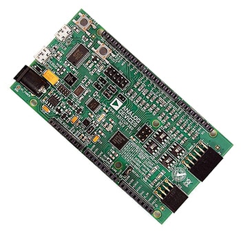
Figure 4a
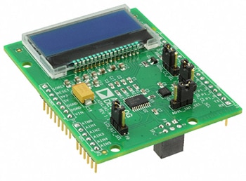
Figure 4b
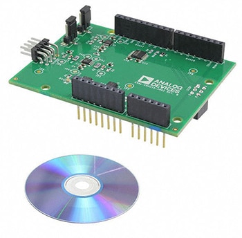
Figure 4c

Figure 4d
Figure 4: Analog Devices' ADUCM360 base board (a) comes in an Arduino Due-compatible form factor (b). Available Analog Devices-branded "shield" expansion boards support accelerometer and weigh scale (c) and toxic gas detection (d) functions. (Images courtesy of Analog Devices)
The ADUCM360 base board also supports the PMOD expansion bus standard, thereby explaining the additional set of connectors shown in Figure 4. Several Arduino Uno R3-format shield expansion boards by Analog Devices are available, supplementing those supplied by the broader Arduino ecosystem:
- The EVAL-ADXL362-ARDZ, based on the ADXL362 3-axis MEMS accelerometer.
- The EVAL-CN0216-ARDZ, a weigh scale signal-conditioning system.
- The EVAL-CN0357-ARDZ, a toxic gas detector using an electrochemical sensor.
Processor evaluation and design considerations
The Arduino boards discussed in this article represent a broad set of processor architectures and associated capabilities. The Atmel ATmega328P, for example, is a relatively straightforward 8-bit RISC CPU implementation, whereas the 64-bit dual-core Intel Atom processor not only runs at higher clock speeds, but is also multi-threaded and otherwise more advanced. The 16- and 32-bit ARM Cortex-M3/M4 and Cortex-A9, as well as the Intel Quark processor, are intermediary options between the earlier two extremes.
On the one hand, as I wrote in another recently published article, Compact, Powerful, Efficient and Cost-Effective ARM-Based Boards Offer Compelling Hardware Options, you don't want to select a CPU that will be too slow for your particular needs, especially if you want to reserve some performance "headroom" for inevitable future software evolution. On the other hand, it makes no sense to pay for much more processor power than you require; keep in mind that your pick will not only have price but also power-consumption impacts. Higher clock speeds may mean little if your software spends most of its time in idle loops awaiting input. Also, advanced architecture features such as superscalar and out-of-order support will only lead to notably higher achievable IPC (instructions per clock) only if there's low instruction-to-instruction dependency in your software.
Similarly, a dearth of thread independence will lead to a limited-at-best throughput advantage for a multi-core CPU versus the simpler single-core alternative, and higher-bit instruction set theoretical advantages may not pan out in your particular application (not to mention their greater memory footprint demands).
Carefully define your particular needs, as that will help you zero in on the preferred processor option(s) of all those covered here. Ideally, your end-system software would already be available, so that you could run it on various candidates and assess their relative strengths and shortcomings. In reality, however, significant portions (if not the entirety) of your code are likely being written in parallel with your hardware development efforts. So you'll instead need to evaluate processor alternatives using software that approximates the functions and routines (specifically the most demanding ones) that you'll be using.
To help you along, there are a variety of benchmark software options. One possibility that bears serious consideration, both for its robustness and its open source nature, is the appropriately named "benchmark" microbenchmark support library sponsored by Google on GitHub. This library contains a number of specific examples, and it's therefore important to run a range of tests representing the various characteristics that will likely be present in your end code in order to gain a comprehensive assessment of each processor alternative.
In basic usage, you define a function that executes the code to be measured:
static void BM_StringCreation(benchmark::State& state) {
while (state.KeepRunning())
std::string empty_string;
}
// Register the function as a benchmark
BENCHMARK(BM_StringCreation);
// Define another benchmark
static void BM_StringCopy(benchmark::State& state) {
std::string x = "hello";
while (state.KeepRunning())
std::string copy(x);
}
BENCHMARK(BM_StringCopy);
BENCHMARK_MAIN();
It's also possible to implement a family of benchmarks via a single routine; an extra argument is used to specify which one of the family of benchmarks to run. The following code, for example, defines a family of benchmarks to measure the speed of different-length memcpy() calls:
static void BM_memcpy(benchmark::State& state) {
char* src = new char[state.range_x()];
char* dst = new char[state.range_x()];
memset(src, 'x', state.range_x());
while (state.KeepRunning())
memcpy(dst, src, state.range_x());
state.SetBytesProcessed(int64_t(state.iterations()) *
int64_t(state.range_x()));
delete[] src;
delete[] dst;
}
BENCHMARK(BM_memcpy)->Arg(8)->Arg(64)->Arg(512)->Arg(1<<10)->Arg(8<<10);
which can alternatively be coded more succinctly, for example this way:
BENCHMARK(BM_memcpy)->Range(8, 8<<10);
For more information, including a number of other reference code segments, see the benchmark project area on GitHub. Happy hunting and good luck!

聲明:各作者及/或論壇參與者於本網站所發表之意見、理念和觀點,概不反映 DigiKey 的意見、理念和觀點,亦非 DigiKey 的正式原則。


