Ultra-Wideband Chip Antennas Upend Tradition to Meet Diverse Applications
The function of an antenna is simply to act as a bidirectional transducer between the RF world governed by Maxwell’s equations and the electrical-circuit world of volts and amperes. Still, it’s astonishing how many different types and sizes of antennas there are in use, including Yagi, bowtie, dipole, loop, dish, patch, dipole, monopole, horn, helical, and stub, just to mention a few.
The reason is that antennas and their configurations have always faced the complex challenge of meeting many, often conflicting objectives. Among the parameters of concern are center frequency, 3-decibel (dB) bandwidth, radiation patterns, directivity, front/back ratio, side lobes, physical size, impedance, and power handling, along with typical size, efficiency, and cost issues.
Ideally, one antenna would fit all, particularly when cost and space become critical. While we’re not there yet, ultra-wideband (UWB) antennas are a good option for many diverse applications that need fast, reliable, low-power connectivity.
Evaluating antennas
Traditionally, one key objective in many systems was to keep the antenna bandwidth (as measured between its -3 dB points) to a minimum to avoid picking up extraneous signals or creating unwanted interference. After all, why support out-of-band performance and added received noise, especially if doing so means compromising on other factors?
One common metric of the bandwidth parameter is the fractional bandwidth (FBW). The FBW is the ratio of the frequency span (highest frequency minus lowest frequency) divided by the center frequency. The fractional bandwidth can range from zero to two and is often quoted as a percentage between 0% and 200%. The higher the percentage, the wider the bandwidth.
It would be nice to have a simple guideline indicating the approximate FBW of different antenna types, but that’s not possible. The reason is that antennas, perhaps more so than most components, have many tradeoffs in their design and physical dimensions. They have an extraordinary number of degrees of freedom, and thus their parameters, including FBW, can be balanced against each other to find an “optimum” design for a given application.
The FBW of almost any antenna can be made larger or smaller by trading off against its other parameters, such as directivity (gain), side lobes, radiation pattern, physical size, and the number of elements for multielement designs. For example, the FBW of classic Yagi-Uda antennas can be adjusted from a few percent to tens of percent by changing the number and spacing of its elements, their thickness, and other physical attributes.
Some specialists consider an antenna with an FBW of 20% or higher to be a UWB antenna, while others say that only those with an FBW above 50% are UWB. The Federal Communications Commission (FCC) and the International Telecommunication Union Radiocommunication Sector (ITU-R) currently define UWB as an antenna transmission for which emitted signal bandwidth exceeds the lesser of 500 megahertz (MHz) or 20% of the arithmetic center frequency. Due to the potential for confusion, it’s often a good idea to ask for clarification when discussing the topic.
UWB: That was then, but needs have changed
Thanks to the advent of wideband and multiband applications, the directive to keep the FBW as narrow as possible has turned around to where a UWB antenna with a large FBW is desirable or even mandated. In fact, there are many recent academic papers describing novel or innovative antenna configurations with UWB characteristics.
Before we continue, let’s discuss UWB terminology. The term “ultra-wideband” (sometimes spelled ultrawideband) has two somewhat different meanings. In the context of antennas, it relates to the FBW, as discussed previously. However, when it comes to the electromagnetic spectrum, the term “ultra-wideband” is also used to describe higher frequencies where more bandwidth is available.
For example, applications that use part of the extremely high frequency (EHF) band from 30 to 300 gigahertz (GHz) are often described as UWB applications since they can use an ultra-wide “slice” of several hundred megahertz to support extremely high data rates. However, such a UWB application using 1 GHz at 60 GHz does not need a UWB antenna; it needs an antenna centered at 60 GHz with an FBW of only about 1.7%.
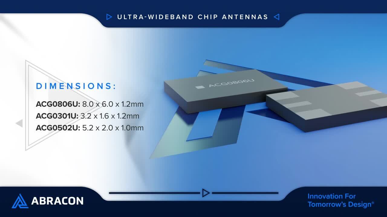
UWB antennas such as the ACG0806U, ACG0301U, and ACG0502U from Abracon operate across this wide range of frequencies. They can be used to replace multiple narrowband antennas while providing a high degree of design flexibility and reliable connectivity (Table 1).
 Table 1: The ACG0806U, ACG0301U, and ACG0502U UWB antennas offer different combinations of frequency range and fractional bandwidth. (Image source: Bill Schweber, from Abracon data)
The potential range of UWB signals and their antennas makes them suitable for applications such as gateways and routers, high-speed streaming, wireless access points, handheld devices, tracking and positioning, smart home device control, and entertainment systems. They are also useful for applications in the Internet of Things (IoT), machine-to-machine (M2M) communications, secure-car access, item tracking, indoor navigation, hands-free payment, smart access, and object detection.
Abracon’s UWB antennas are also designed for next-generation of connectivity. They cover the entire spectrum from 698 MHz to 7 GHz and offer multiple benefits:
- High performance
- High radiated efficiency
- Low power consumption (due to the low power requirements of UWB systems)
- Meet industry needs for fast/stable data transmission
- Complete, discrete chip devices to simplify antenna design-in and board/system layout
Highlighting the specifics
A closer look at an Abracon UWB antenna shows both its attributes and how it eases the engineering design effort. The ACG0806U is a surface mount device (SMD) UWB antenna for 3.3 GHz to 7.2 GHz operation (4000 MHz bandwidth) in a tiny 8.0 × 6.0 × 1.2 millimeter (mm) ceramic chip package (Figure 1).
 Figure 1: The Abracon ACG0806U is a UWB antenna for 3.3 GHz to 7.2 GHz operation in a tiny 8.0 mm × 6.0 mm × 1.2 mm SMD ceramic chip package. (Image source: Abracon)
Electrically, the ACG0806U offers linear polarization and an omnidirectional azimuth beam width, with a 50 ohm (Ω) nominal impedance and a voltage standing wave ratio (VSWR) under 3.5. Further details of its performance include graphs showing the impedance characteristic of return loss and the radiation characteristic of total efficiency (Figure 2 and Figure 3).
 for the ACG0806U detailing one aspect of its performance across its specified band of operation") Figure 2: The graph of return loss (in dB) for the ACG0806U details one aspect of its performance across its specified band of operation. (Image source: Abracon)
Figure 2: The graph of return loss (in dB) for the ACG0806U details one aspect of its performance across its specified band of operation. (Image source: Abracon)
 Figure 3: Shown is the efficiency of the ACG0806U across its operating frequency. (Image source: Abracon)
Just as important for designers is how and where to place and interface with the chip antenna. For the ACG0806U, an evaluation board shows the critical dimensions and associated matching circuitry (Figure 4).
 Figure 4: Shown are the relevant dimensions for placement of the ACG0806U antenna. (Image source: Abracon)
Conclusion
UWB antennas are needed to support the diverse multiband and wideband applications that are now getting greater attention. Abracon offers a selection of surface mount UWB chip antennas with different center frequencies and bandwidths. Using these, designers can quickly select and site a UWB antenna on their circuit board and move on to the next stages of their project.
Recommended Reading
1: Beyond Wires: Antennas Evolve and Adapt to Meet Demanding Wireless Requirements
https://www.digikey.com/en/blog/beyond-wires-antennas-evolve-and-adapt
2: How to Cater to Both Legacy and 5G Wireless IoT Networks Using Wideband Antennas
References
1: International Journal of Antennas and Propagation, “Wideband and UWB Antennas for Wireless Applications: A Comprehensive Review”
https://www.hindawi.com/journals/ijap/2017/2390808/
2: IntechOpen, “Ultra-Wideband Antenna and Design”
https://www.hindawi.com/journals/ijap/2017/2390808/
3: National Institute of Health, National Library of Medicine, “Ultrawideband Antennas: Growth and Evolution”
About this author

Bill Schweber is an electronics engineer who has written three textbooks on electronic communications systems, as well as hundreds of technical articles, opinion columns, and product features. In past roles, he worked as a technical web-site manager for multiple topic-specific sites for EE Times, as well as both the Executive Editor and Analog Editor at EDN.
At Analog Devices, Inc. (a leading vendor of analog and mixed-signal ICs), Bill was in marketing communications (public relations); as a result, he has been on both sides of the technical PR function, presenting company products, stories, and messages to the media and also as the recipient of these.
Prior to the MarCom role at Analog, Bill was associate editor of their respected technical journal, and also worked in their product marketing and applications engineering groups. Before those roles, Bill was at Instron Corp., doing hands-on analog- and power-circuit design and systems integration for materials-testing machine controls.
He has an MSEE (Univ. of Mass) and BSEE (Columbia Univ.), is a Registered Professional Engineer, and holds an Advanced Class amateur radio license. Bill has also planned, written, and presented on-line courses on a variety of engineering topics, including MOSFET basics, ADC selection, and driving LEDs.

Have questions or comments? Continue the conversation on TechForum, DigiKey's online community and technical resource.
Visit TechForumRelated Blogs


More Blogs from this Author