The Right Connector Can Tame Both Radiated and Conducted EMI
Electromagnetic interference (EMI) is a frustrating and often inevitable reality in many system designs. It is pervasive and pernicious, and its effects worsen as operating frequencies increase. It can be radiated through the air or conducted via signal and power lines, which then inject it into the circuit or act as antennas to transmit it.
If a product conducts or radiates EMI (the “aggressor”), it can interfere with the functioning of nearby systems, fail regulatory compliance testing, and be kept off the market. In contrast, if a product is in the opposite role as a deliberate or unintentional recipient of EMI (a “victim”), it may suffer from unexplainable and intermittent faults, failures, and inconsistencies.
These issues may range from life-threatening, such as in an airplane or hospital, to costly, such as in a production line, to mildly humorous, as in the case of my wireless bike speedometer. The speedometer operates in the 432 megahertz (MHz) band and, for some reason, consistently reads 65 to 85 miles per hour (MPH) over a 100 yard stretch of road between an isolated house and nearby Amtrak tracks with 20 kilovolt (kV) overhead lines.
How to minimize the effects of EMI
Reducing or eliminating the source of EMI or its impact is both simple and challenging. The basic steps include adequate grounding, thorough shielding, proper bypassing, and, of course, the use of filters. Beyond those steps, it is often the usual “80/20” story: eliminating 80% takes 20% of the effort; getting rid of the remaining 20% can easily be 80% of the work.
Any gap in an enclosure, such as that required for a connector plug and receptacle, is a door through which EMI energy can pass in either direction. However, if EMI is due solely to radiated energy, a shielded connector solves the problem.
This problem was addressed decades ago, beginning with the application of coaxial cable and the classic SO-239 and PL-259 female and male connectors, as well as the BNC series. However, these fully shielded RF connectors can only support one signal per connector and are not suitable for DC power and non-RF signals.
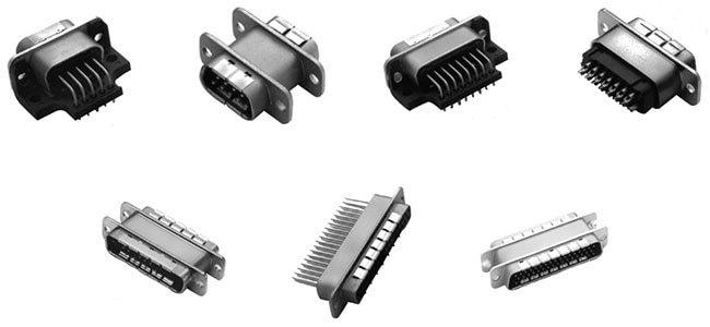
A good alternative is to go “back to the future” to a connector type that was once dominant for communication links and other interfaces: the D-subminiature (D-sub) connector (Figure 1) from companies such as Molex. Before USB and parallel ports, engineers and many consumers used this connector in its 9-pin version (called DB-9) as the interconnect for the RS-232 serial protocol.
 Figure 1: The widely used, rugged D-sub connector and adapter series comes in a broad range of contact positions, electrical ratings, EMI-filtering bandwidths, and physical terminations; pi filters address conducted EMI. (Image source: Molex)
USB and Ethernet have largely taken over the role of RS-232, so the protocol is now primarily found in legacy systems and is rarely used in new designs; yet, the D-sub connector lives on. There are many reasons for its longevity:
- The gap-free metal-on-metal design provides 100% shielding around the wires.
- It is mechanically rugged, allowing for the use of posts and jackscrews for positive locking between the mating pairs.
- Versions with 9, 15, 25, 37, and 50 contacts are available.
- It is offered with a wide range of terminations, including solder cups and straight or right-angle printed circuit board (pc board) pins.
When shielding alone is not enough
The shielding of the D-sub connector addresses the radiated EMI energy problem but does not resolve the conducted EMI issue. That’s where the Molex family of EMI-filtered, high-performance, D-sub pi adapters and connectors (Figure 1, again) becomes an attractive solution.
These connectors incorporate EMI filters in their contacts, so no additional space or components are required on the pc board. Both grounded and insulated lines are within the same connector to further save space. They are available in an extensive range of mechanical configurations and terminations for design-in options.
The integral filters prevent conducted EMI from passing through the connector pair, thereby attenuating EMI in critical situations, such as engine controls in aircraft, airborne radios, imaging equipment, processing equipment, and many other applications.
Key adapter and connector features include:
- Construction: The one-piece die-cast shell and fully soldered internal structure reinforce both mechanical and electrical performance, preventing failures in high-vibration environments. The connectors are compatible with the M24308 (MIL-DTL-24308) standard. Their glass-filled polyester body also meets the UL 94 V-0 flammability standard.
- Electrical ruggedness: The connectors can withstand lightning and AC-transient environment conditions up to DO-160 Level IV for environmental testing of airborne hardware.
- Electrical filtering: Using a three-element pi configuration (capacitor, inductor, and capacitor), the filters absorb high-frequency noise in power and signal lines. Their sharp attenuation slope supports the suppression of broadband EMI.
- Feedthrough capacitors: To prevent unwanted signal transfer at interconnect points, feedthrough capacitors provide a low-impedance path to ground. They effectively reduce conducted emissions, especially in shielded enclosures where traditional capacitors fall short.
- Inductive elements (ferrites, toroids): These elements absorb high-frequency energy and dissipate it as heat, minimizing unintended coupling.
The EMI filtering cutoff frequency is selected by the user, as these connectors are offered with a wide range of capacitances and thus cutoff frequencies, along with their associated insertion losses (Figure 2).
 Figure 2 : Users of the EMI-filtered, high-performance D-sub pi adapters and connectors can select from a range of parameters to suit application requirements. (Image source: Molex)
The contacts have a maximum resistance of 10 milliohms (mΩ) and can handle up to 5 amperes (A) (RF current of 0.3 A), with a working voltage rating of 50 or 100 volts, depending on the model.
Two examples out of many possibilities
To meet the needs of designers for a specific number of contact positions, cutoff frequencies, and mounting options, this Molex family offers connectors and adapters that span 9 to 50 contact positions, multiple capacitances, and various termination types.
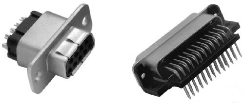
For example, the 0732843041 (Figure 3, left) is a 9-contact female-socket connector with capacitance options from 100 to 4000 picofarads (pF) and solder-cup terminations designed for direct wire attachment. Another option is the 0732840290 (Figure 3, right), a 25-contact male-plug connector featuring the same capacitance options but with two rows of right-angle pin terminations for direct soldering to a pc board.
 Figure 3: The 9-contact 0732843041 female-socket connector (left) has solder cups for attachment of individual wires; the 0732840290 is a 25-contact male-plug connector (right) that has two rows of right-angle pin terminations for soldering to a pc board. (Image source: Molex)
Conclusion
Experienced engineers know that connectors are as crucial to product success as any other active or passive component. The Molex EMI-filtered, high-performance D-sub pi adapters and connectors do more than just provide continuity. They can provide significant attenuation of radiated and conducted EMI. By doing so, they reduce design uncertainties and unwanted EMI surprises.
Related Content
1: Basics of Connectors
https://www.digikey.com/en/blog/basics-of-connectors
2: Taming EMI and RFI
https://www.digikey.com/en/maker/blogs/2024/taming-emi-and-rfi
3: What Are EMC and EMI?
https://www.digikey.com/en/blog/what-are-emc-and-emi
4: An Introduction to EMI and EMC Measurement of Power Supplies - Part 1: Conducted EMI
https://www.digikey.com/en/blog/an-introduction-to-emi-and-emc-measurement-of-power-supplies-part-1
5: An Introduction to EMI and EMC Measurement of Power Supplies—Part 2: Radiated EMI
https://www.digikey.com/en/blog/an-intro-to-emi-and-emc-measurement-of-power-supplies-pt-2

Have questions or comments? Continue the conversation on TechForum, DigiKey's online community and technical resource.
Visit TechForum


