Antenna’s Innovative Materials and Design Solves the Multiband GNSS Dilemma
Since its beginnings in the late 1970s and into the 1980s under the auspices of the United States (US) Department of Defense (DoD), the roles and applications of the Global Positioning System (GPS) have expanded exponentially. Originally intended solely for navigation and missile guidance, it is now integrated into asset tracking and monitoring, autonomous vehicles, agriculture, wearables, and many other end uses that its originators never envisioned.
Following the successful deployment of GPS in the US, other countries and regions developed and launched their GPS equivalents, collectively referred to as the Global Navigation Satellite System (GNSS). GNSS includes GLONASS (Russia), Galileo (European Union), and BeiDou (China), as well as two regional GNSS systems: QZSS (Japan) and IRNSS/NavIC (India).
While the original GPS receiver system was large and barely fit into the trunk of a car, modern technology has reduced the GNSS core engine to a single integrated circuit (IC). Regardless of the GNSS type, all these systems need an antenna optimized to receive the extremely low-level RF signals from the array of GNSS satellites. As GNSS receivers have shrunk in size and reduced their power requirements, the size of the antenna has had to shrink accordingly.
However, this presents a challenge for the receivers, which must handle more than one GNSS system or band. They require an antenna that can handle both the lower and upper RF bands of the different systems in use (Figure 1).
 Figure 1 : The defined GNSS frequency assignments and bands for various systems in use show both overlap and separation. (Image source: Taoglas Limited)
The GNSS bands and frequencies have these designations:
- 1,559 to 1,610 megahertz (MHz), referred to as L1, E1, B1
- 1,215 to 1,300 MHz, referred to as L2, E6, B3, L6
- 1,164 to 1,215 MHz, referred to as L5, E5, B2, L3
Note that L-band refers to the frequency range of 1,525 to 1,559 MHz, which is used by various satellites to transmit correction signals.
The need for wideband or multiband antennas dates back to the early days of wireless communication in the early 20th century, and there are two general approaches. One is to use physical “traps” or loading coils to make a single narrowband antenna resonant at two distinct center frequencies. The other option is to use a single antenna that is inherently designed for wideband performance.
Neither of these solutions is desirable for GNSS antennas in today’s compact system designs. The trap approach requires relatively large discrete inductors and capacitors, whereas the broadband antenna compromises attributes critical to performance, such as gain and efficiency.
A superior antenna approach
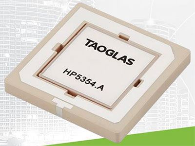
A better solution is now available via Taoglas Limited’s Inception Series. For example, the HP5354.A (Figure 2) is a multiband, 1,160 to 1,610 MHz passive GNSS patch antenna designed for enhanced position accuracy. This innovative ceramic patch-within-a-patch antenna features optimized gain for BeiDou (B1/B2a), GPS/QZSS (L1/L5), GLONASS (G1), and Galileo (E1/E5a) bands.
 Figure 2: The HP5354.A is a compact, low-profile antenna optimized for dual-band (L1 and L5) GNSS performance. (Image source: Taoglas Limited)
The HP5354.A measures 35 × 35 millimeters (mm), and its 4 mm height makes it a good fit for compact, low-profile designs. The 11-pin package uses three of its pins for received signal interfaces (two for the L1 band and one for the L5 band), while the remaining pins serve as grounds.
The multiple-feed HP5354.A has been tuned and tested with a 70 × 70 mm ground plane and has excellent radiation patterns. It can cover the bands required for the next generation of L1/L5 GNSS and is fully characterized across both bands for key frequency-dependent parameters, including return loss, voltage standing wave ratio (VSWR), efficiency, average gain, peak gain, axial ratio, phase center offset, phase center variations, and group delay.
Applying the Taoglas HP5354.A
Although the HP5354.A can be paired with a user-provided front-end module, Taoglas simplifies the development of the low-level signal chain with the TFM.100B GNSS RF module. This high-performance module covers the L1 and L5 bands and is specifically engineered for use with multifeed patches.
The TFM.100B features a two-stage, low-noise amplifier (LNA) that provides over 25 decibels (dB) of gain across all bands, along with a low noise figure of less than 3 dB. The module features a surface acoustic wave (SAW)/LNA/SAW/LNA topology in both the low-band and high-band signal paths to prevent unwanted out-of-band (OOB) interference from overdriving the GNSS LNAs or the receiver.
The SAW filters within the TFM.100B have been carefully selected and placed to provide excellent OOB rejection while also maintaining the low 3 dB noise figure. This easy-to-integrate surface-mount device measures 20 × 18 mm and operates from a single 1.8 to 5.5 volt DC (VDC) supply.
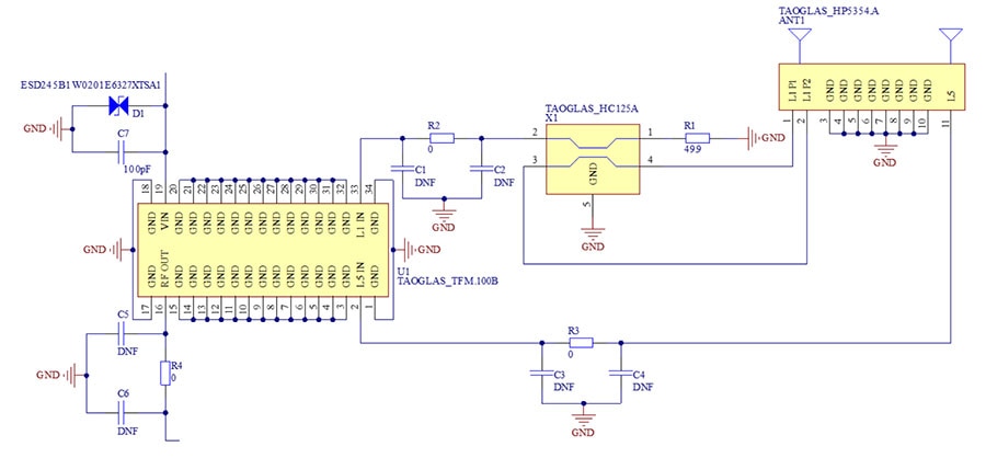
Taoglas further simplifies HP5354.A integration into a complete system by providing the AHPD5354A evaluation board (Figure 3). The board features the TFM.100B RF preamplifier and the Taoglas HC125A, a low-profile, high-performance, 3 dB hybrid coupler designed for multi-feed multiband GNSS applications. The HP5354.A, TFM.100B, and HC125A work together as an integrated signal chain.
 Figure 3 : The AHPD5354A evaluation board features a hybrid coupler for L1/L5 signals and a full-featured RF preamplifier and filter, providing a complete RF signal chain. (Image source: Taoglas Limited)
The HP5354.A provides two orthogonal feeds via three pins, with two pins for the L1-band antenna output and the other pin for the L5-band output. These feeds are combined in the hybrid coupler for the L1 band to ensure optimal axial ratio and create a right-hand circular polarized (RHCP) signal, which is then presented to the corresponding inputs on the TFM.100B.
Note that the HC125A hybrid coupler is only required for the high GNSS band of operation for this antenna (1,559 to 1,610 MHz). The evaluation board layout diagram illustrates how the hybrid coupler should be positioned near the antenna pins and properly terminated using two 100 ohm (Ω) resistors in parallel.
Conclusion
The ubiquitous GNSSs use sophisticated core ICs and advanced algorithms for the computations needed to determine receiver position. Providing the raw signals to these ICs is the challenge of the RF signal chain, which begins with the receiver antenna. The Taoglas HP5354.A is a tiny, dual-band, surface-mount antenna that simultaneously supports both lower and upper GNSS frequency bands. When used in conjunction with the Taoglas hybrid coupler and low-noise preamplifier devices, designers have a straightforward solution for implementing an RF front-end for GNSS receivers.
Related Content
- Inception Series GNSS L1/L5 Patch-in-a-Patch Antenna
- Why High-Reliability Antennas Are Key in Data Center AI Applications
- Cutting That Whip Antenna Down to Size
- Use Traps to Enable Multiband Operation with Dipole Antennas
- Antenna Polarization: What It Is and Why It Matters
- Simplifying GNSS Product Development on the Front End
- Taoglas, Navigating the L1, L2 and L5 Band Options for GNSS
- How to Choose Between a Dual-Band or Multi-Band GNSS Antenna
https://www.digikey.com/en/product-highlight/t/taoglas/inception-series-patch-in-a-patch-antenna
https://www.digikey.com/en/blog/why-high-reliability-antennas-are-key
https://www.digikey.com/en/blog/cutting-that-whip-antenna-down-to-size
https://www.digikey.com/en/blog/use-traps-to-enable-multiband-operation-with-dipole-antennas
https://www.digikey.com/en/blog/antenna-polarization-what-it-is-and-why-it-matters
https://www.digikey.com/en/blog/simplifying-gnss-product-development-on-the-front-end
https://www.taoglas.com/blogs/navigating-l1-l2-and-l5-band-options-for-gnss/
https://www.taoglas.com/blogs/how-to-choose-between-a-dual-band-or-multi-band-gnss-antenna/

Have questions or comments? Continue the conversation on TechForum, DigiKey's online community and technical resource.
Visit TechForum


