Antenna Polarization: What It Is and Why It Matters
Electronic engineers understand that antennas radiate and receive signals in the form of electromagnetic (EM) energy waves as characterized by Maxwell’s equations. As with many topics, these equations—along with EM propagation and attributes—can be examined at various levels from relatively qualitative terms to complicated equations.
Polarization is one of the many aspects of EM energy propagation that can have varying degrees of impact or concern in an application and its antenna design. Its basic principles apply to all EM radiation, including RF/wireless and optical energy, and it is often used in optical applications. Here, we’re only looking at RF.
What is antenna polarization?
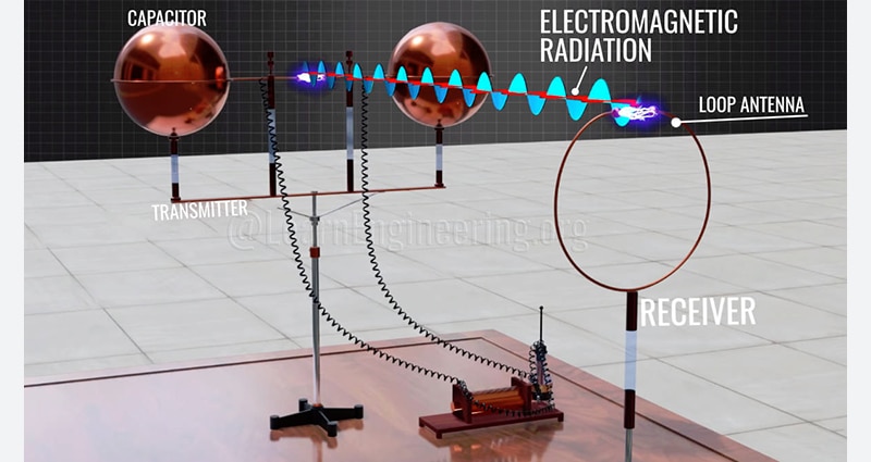
Understanding polarization begins with the basics of EM waves. These waves consist of an electric field (E-field) and a magnetic field (H-field) traveling in a single direction. The E-field and H-field are perpendicular to each other and also to the direction along which the plane wave is propagating.
Polarization refers to the plane of the E-field from the perspective of looking at it from the transmitter of the signal: for horizontal polarization, the electric field will move sideways in a horizontal plane, while for vertical polarization, the electric field will oscillate up and down in a vertical plane (Figure 1).
 Figure 1: An electromagnetic energy wave consists of E-field and horizontal-field components at right angles to each other. (Image source: Electronic-Notes)
A transmit and receive antenna pair work best when the polarization of the transmit and receive antennas are in the same plane. Of course, just as “in space, no one can hear you scream” (apologies and a nod to the classic 1979 movie Alien). It is also true that there is no horizontal or vertical in space. Nonetheless, the concept of polarization and antenna alignment for maximum signal energy transfer and capture is still valid.
Linear and circular polarization
There are several polarization modes:
• In basic linear polarization, the two possible polarizations are orthogonal (at right angles) to each other (Figure 2). In theory, a receiving antenna with horizontal polarization would not “see” a signal from one with vertical polarization and vice versa, even if the two are operating at the same frequency. The closer their alignment, the more signal is captured, with maximum energy transfer taking place when the polarizations are matched.
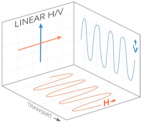 Figure 2: Linear polarization offers a choice of two polarizations at right angles to each other. (Image source: Mimosa Networks, Inc.)
• Slant polarization of an antenna is a variation of linear polarization. As with basic horizontal and vertical polarization, it only has meaning in a terrestrial context. Slant polarization is at ±45 degrees from a horizontal reference plane. Although this is really just another form of linear polarization, the term linear generally refers only to antennas that are horizontally or vertically polarized.
A signal sent (or received) by a slant antenna will be viable for use with a horizontal or vertical-only polarized antenna, although with some loss. A slant-polarized antenna is useful when the polarization of one or both antennas is unknown or changes during use.
• Circular polarization (CP) is more complicated than linear polarization. In this mode, the polarization represented by the E-field vector rotates as the signal propagates. When it rotates to the right, looking out from the transmitter, the polarization is referred to as right-hand circular polarization (RHCP); when it rotates to the left, it’s known as left-hand circular polarization (LHCP) (Figure 3).
 Figure 3: In circular polarization, the E-field vector of the EM wave rotates; this rotation can be either right-handed or left-handed. (Image source: JEM Engineering)
A CP signal consists of two orthogonal waves that are out of phase. Three conditions are needed to create it. The E-field must have two orthogonal components; they must be 90 degrees out of phase and have equal magnitude. One simple way to create CP is to use a helical antenna.
• Elliptical polarization (EP) is a variation of CP. Elliptically polarized waves are gain generated from two linearly polarized waves, like CP waves. When two mutually perpendicular linearly polarized waves with unequal amplitude are combined, the elliptically polarized wave is produced.
Polarization mismatch between antennas is characterized by polarization loss factor (PLF). The parameter is expressed in decibels (dB) and is a function of the angular difference in polarization between the transmit and receive antennas. In theory, PLF can range from 0 dB (no loss) for perfectly aligned antennas to infinite dB (infinite loss) for perfectly orthogonal antennas.
In practice, however, the alignment (or misalignment) of polarization is not perfect, as the antennas mechanical position, user actions, channel distortion, multipath reflections, and other phenomena cause some angular twisting of the transmitted EM field. Initially, orthogonal polarizations can have a signal cross-polarization “leakage” of 10 to 30 dB or more, which may be enough to interfere with desired signal recovery in some cases.
Conversely, two antennas with ideal polarization and alignment may have an actual PLF of 10, 20, or more dB, depending on the specifics of the situation, which may impede signal recovery. In other words, unintended cross-polarization and PLF work both ways by interfering with the desired signal or decreasing the strength of the desired signal.
Why care about polarization?
Polarization works in two ways: the more closely two antennas are aligned and have the same polarization, the better the received signal strength will be. Conversely, poorly aligned polarization can make it more difficult for an intended or undesired receiver to capture enough useful signal. In many cases, the “channel” distorts the transmitted polarization, or one or both antennas are not in fixed, static orientations.
The choice of which polarization to use, is typically determined by the installation or atmospheric conditions. For example, a horizontally polarized antenna will perform better and retain its polarization when mounted near a ceiling; in contrast, a vertically polarized antenna exhibits polarization performance that is closer to nominal when mounted near a side wall.
The widely used dipole antenna (regular or folded) is horizontally-polarized in its “normal” mounting orientation (Figure 4) and often rotated by 90 degrees to present a vertical polarization if needed or to support a preferred polarization mode (Figure 5).
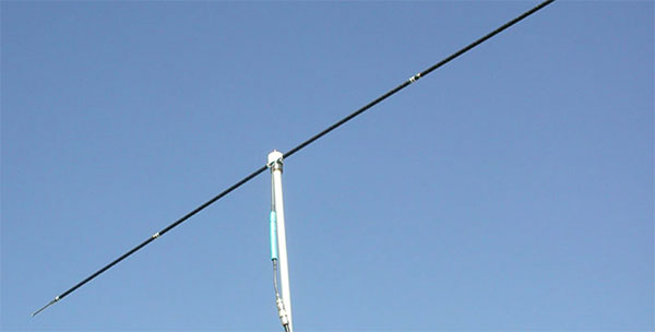 Figure 4: A dipole antenna is usually mounted horizontally on its mast to provide horizontal polarization. (Image source: KAC Radio)
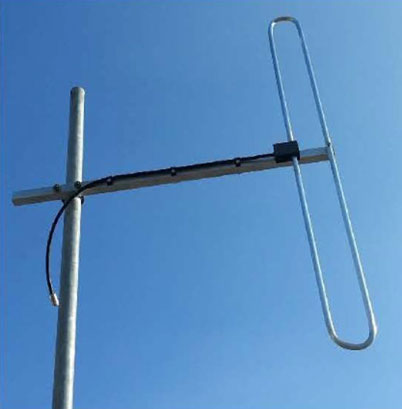 Figure 5: For applications where vertical polarization is required, the dipole antenna can be mounted accordingly on the mast. (Image source: Progressive Concepts)
Vertical polarization is often used for handheld mobile radios, such as those used by first responders because many vertically polarized radio antenna designs also provide an omnidirectional radiation pattern. Consequently, these antennas do not have to be reoriented, even as the radio and antenna orientation changes.
Antennas for the high frequency (HF) band of 3 to 30 megahertz (MHz) are often constructed as simple long wires strung horizontally between supports. This long length is dictated by the wavelength (10 to 100 meters (m)). These antennas are naturally horizontally polarized.
It’s interesting to note that the use of the designation “high frequency” for this band was established many decades ago when 30 MHz was indeed a high frequency. While that characterization may now seem archaic, it is an official International Telecommunications Union designation that is still widely used.
The preferred polarization may also be determined by whether the broadcaster in the medium wave (MW) band of 300 kilohertz (kHz) to 3 MHz is using ground waves for stronger, close-in signal propagation, or sky waves via the ionosphere for long-distance links. In general, ground-wave propagation is better with a vertically polarized antenna, while sky-wave performance is better with horizontal polarization.
Circular polarization is widely used with satellites as their orientation with respect to the ground station and other satellites is constantly changing. Maximum efficiency between transmitting and receiving antennas occurs when both the antennas are circularly polarized, but a linearly polarized antenna can be used in conjunction with a CP antenna, with some polarization loss factor.
Polarization is also important to 5G systems. Some 5G multiple input/multiple output (MIMO) antenna arrays achieve increases in throughput through more efficient use of available spectrum via polarization. This is done using a combination of different signal polarization and spatial multiplexing (spatial diversity) of the antennas.
The system can transmit two data streams since they are connected to separate antennas with orthogonal polarizations that can be recovered independently. Even if there is some cross-polarization due to path and channel distortion, reflections, multipath, and other imperfections, sophisticated algorithms at the receiver can still recover each original signal to yield a low bit error rate (BER), improving spectrum utilization.
Standard antennas offer polarization options
It’s easy to assume that polarization is only an issue with large, mast-mounted, highly visible antennas, but that is not the case. For example, the PCTel BOAH515905NM is a horizontally polarized Wi-Fi antenna for use from 5.1 GHz to 5.9 GHz, primarily targeting outdoor 802.11ac access points (Figure 6).
 Figure 6: The PCTel BOAH515905NM horizontally polarized Wi-Fi antenna is designed to provide an outdoor access point for 5.1 GHz to 5.9 GHz (802.11 ac) Wi-Fi connectivity. (Image source: PCTel)
The fully sealed, IP67-rated antenna is housed in a white, ultra-violet (UV) stable, ruggedized plastic radome that includes an integral N-type panel-mount connector (male and female versions are available). It measures 1.26 inches OD × 6.32 inches long (3.20 x 16.1 centimeters), provides 5 dBi nominal gain, and has a voltage standing wave ratio (VSWR) that is below 2:1 across the designated band.
Polarization can also be designed into much smaller antennas. The Taoglas PC140.07.0100A is a circularly polarized 2.45 GHz (nominal) antenna for Industrial, Scientific, and Medical (ISM), Bluetooth, and Wi-Fi applications (Figure 7).
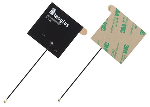 Figure 7: This tiny PC140.07.0100A antenna from Taoglas is designed to be embedded in an enclosure alongside the system’s circuit board. (Image source: Taoglas)
This tiny 50 ohm (Ω) antenna, just 57 × 57 millimeters (mm) square and 0.97 mm thick, comes with a coaxial cable 1.13 mm in diameter, 100 mm long, and terminated in an IPEX connector (a standard 50 Ω surface-mount connector that is soldered directly to the printed circuit (pc) board). The antenna is made from FR-4 circuit board material and is easily mounted using its integral adhesive patch.
The radiation pattern of this antenna is highly omnidirectional, as seen from its X-Y and X-Z radiation patterns (Figure 8). Its VSWR is below 2:1, and its efficiency is around 60% across the 2.4 to 2.5 GHz band of operation.
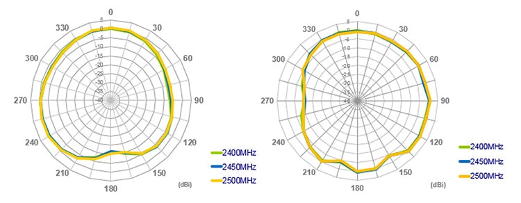 Figure 8: The radiation patterns of the Taoglas PC140.07.0100A show its fairly omnidirectional nature in both X-Y (left) and X-Z (right) planes. (Image source: Taoglas)
Conclusion
Polarization is an important antenna attribute that is often overlooked. Linear (both horizontal and vertical), slant, circular, and elliptical polarizations are used in different applications. They provide ranges of end-to-end RF performance depending on their relative orientation and alignment. Standard antennas are available with different polarizations and for different parts of the spectrum, providing the preferred polarization for the target application.
Related Content
1: How to Cater to Both Legacy and 5G Wireless IoT Networks Using Wideband Antennas
2: Beyond Wires: Antennas Evolve and Adapt to Meet Demanding Wireless Requirements
https://www.digikey.com/en/blog/beyond-wires-antennas-evolve-and-adapt
3: Use PIFAs to Solve the Small-Product, Smaller-Antenna Dilemma
https://www.digikey.com/en/blog/use-pifas-to-solve-the-small-product-smaller-antenna-dilemma
4: Antennas: Design, Application, and Performance
https://www.digikey.com/en/articles/antennas-design-application-and-performance
5: Antennas: The Critical Link for High-Speed Wireless Networks
https://www.digikey.com/en/articles/antennas-the-critical-link-for-high-speed-wireless-networks
6: A Multi-band Hybrid Balanced Antenna
https://www.digikey.com/en/articles/a-multi-band-hybrid-balanced-antenna
7: Selecting Antennas for Embedded Designs
https://www.digikey.com/en/articles/selecting-antennas-for-embedded-designs
8: Range Measurements in an Open Field Environment
https://www.digikey.com/en/articles/range-measurements-in-an-open-field-environment
References
1: JEM Engineering, “Intro to Antenna Polarization”
https://jemengineering.com/blog-intro-to-antenna-polarization/
2: Mimosa Networks, Inc., “Antenna Polarization Basics”
https://mimosa.co/white-papers/antenna-polarization
3: Mimosa Networks, Inc., “Demystifying Antenna Polarizations”
https://mimosa.co/white-papers/antenna-polarization-2
4: Electronics-Notes, “Antenna Polarization”
5: Antenna-theory.com, “Polarization of Plane Waves”
https://www.antenna-theory.com/basics/polarization.php
6: Electronics Desk, “Antenna Polarization”
https://electronicsdesk.com/antenna-polarization.html
https://www.mpantenna.com/antenna-polarization-explained/
7: MP Antenna, Ltd., “Antenna Polarization Explained”

Have questions or comments? Continue the conversation on TechForum, DigiKey's online community and technical resource.
Visit TechForum


