Beyond Wires: Antennas Evolve and Adapt to Meet Demanding Wireless Requirements
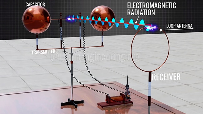
Antennas are truly wondrous devices. They are simultaneously magical, mystical, and absolutely essential to our wireless world. Since Heinrich Hertz first used a spark gap—a crude type of antenna—in the 1880s to send signals as wireless energy across a table, antenna design and implementation has been critical to the success of wireless devices and the communication links they support (Figure 1).
 Figure 1: This is a modern version of the arrangement used by Heinrich Hertz to investigate the mysterious phenomena we now know as the transmission of power via wireless electromagnetic fields. (Image source: Lesics Engineers Pvt. Ltd.)
So, what exactly does an antenna (called an “aerial” in the UK) do? From a physics and power perspective, it is a transducer between the electrical power of a circuit represented by volts and amps and a free-space electromagnetic (EM) field as characterized by Maxwell’s equations. We’ll get into the physics of this a bit more in a subsequent blog, but for now, suffice it to know they exhibit reciprocity and are directionally agnostic, as they are capable of radiating electrical power from a circuit out to free space, and also capturing ambient EM power and delivering it to a circuit.
An antenna can be a very simple length of wire or a mind-bogglingly complex configuration with many elements, careful geometric arrangements, and sophisticated interconnections. Their sizes also span a range from millimeters to huge arrays occupying tens of acres, with the size being a function of frequency, power, and other needed performance characteristics, as well as the space constraints of the system they support.
As with all components, they are initially characterized by several top-tier parameters followed by many secondary ones. Of course, in some applications, a secondary attribute may also be very important. Among the primary attributes of interest are:
- Operating frequency: The center of the frequency or band over which the antenna provides useful performance.
- Bandwidth: The width of spectrum over which the antenna operates and whether it is a single or multi-band design.
- Efficiency: The ability to radiate or capture electromagnetic energy.
- Radiation: The pattern in a 360⁰ horizontal plane (azimuth) and the vertical (elevation) plane (Figure 2).
 Figure 2: Among the many antenna attributes of interest are the azimuth and elevation radiation patterns. (Image source: VCEguide)
There is no simplistic good/better/best ranking for each of these factors. For example, some applications need more bandwidth while others require less to best meet the application requirements.
While the ideal antenna would look like a purely resistive load at its operating frequency (typically 50 or 75 Ω), the impedance of most real antennas has a reactive component as well. At the same time, the transmitter output driving the antenna (or the receiver connected to the antenna) has its own reactive non-resistive impedance. The combination of these two realities often requires matching these impedances.
Contrary to intuition, “matched impedance” does not mean that these impedances are equal. Instead, it means that the source impedance and the load impedance are complex conjugates of each other, a condition that results in the maximum power transfer between the two. As with antennas, there are countless arrangements, components, and techniques available to implement the impedance transformation to provide this matching, including using discrete passive components (Figure 3).
 Figure 3: This representative balun circuit uses capacitors and resistors to provide impedance matching to an antenna that has both resistive and inductive impedance components. (Image source: ResearchGate)
For the transmitter-to-antenna link, the goal is to bring the voltage standing wave ratio (VSWR) close to unity, meaning efficient power transfer with no reflected power coming back to the source.
Don’t be overwhelmed
Given the infinite types and configurations of antennas, the entire topic can seem overwhelming. Fortunately, there is a basic point to keep in mind: nearly all antennas are built up from one of two fundamental blocks. These are the single-element “unbalanced” monopole antenna with a real (or virtual) ground plane and characterized by the long wire or whip design (Figure 4) and the balanced, ungrounded, dipole antenna (Figure 5). These basic elements are often used alone, but they are also used to form larger, more complex antenna configurations.
 Figure 4: The long wire or whip antenna arrangement is a single-element design using a ground plane (here, the car’s roof, left); the diagram of the antenna shows its simplicity (right). (Image sources: Lihong Electronic; Electronics Notes)
 Figure 5: The basic dipole is a balanced, symmetrical antenna without a ground reference (left), as illustrated by its diagram (right). (Image sources: TCARES.net; Tutorials Point)
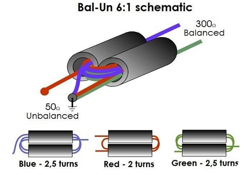
An adapter called a balun (short for balanced-unbalanced) implements an electrical transition between an unbalanced grounded circuit and a balanced, ungrounded dipole if needed, and can also transform the impedance (in ohms (Ω)) for a resistive match between source/receiver and antenna (Figure 6).
 Figure 6: This passive balun transforms a 50 Ω unbalanced impedance to a 300 Ω balanced one. (Image source: Pinterest)
As applications have advanced in frequency, complexity, and flexibility, so have antenna systems. For example, 5G access points use multiple antennas in a phased-array arrangement where the individual antenna elements are electronically steered by phase-shifting of their feeds; this is an evolution of technology originally used in military radars which, in turn, replaced mechanical movement of the entire antenna assembly.
Other antennas are tiny dielectric ceramic resonators, which are miniaturized chip-scale antennas with metalized ground planes. Still, others use the printed circuit board (pc board) of the end-product for their ground plane (single-ended) or dipole-antenna elements.
Given the complexity of antennas and their possible configurations, how do you select one for your application? You start with the thousands of antennas of all sizes and performance attributes that are available as off-the-shelf or standard-catalog items. These antennas come with detailed data sheets calling out their real-world, tested performance and characteristics.
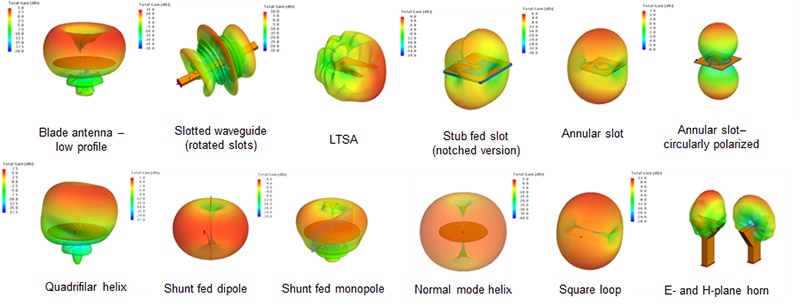
If a new antenna design is needed to meet unique size, frequency, or performance attributes, modern simulation and modeling tools are extremely powerful. These EM field solvers can model the electric and magnetic field performance (the E and H fields, respectively) of nearly any antenna configuration (Figure 7).
 Figure 7: Advanced EM field modeling tools can quantitatively assess the performance of simple and complex antenna configurations. (Image source: Altair Engineering, Inc.)
These tools are now sufficiently sophisticated enough to account for real-world antenna issues, such as EM field “fringing” effects at the ends of the elements and their non-zero thickness. They can even model the effects of adjacent components and surfaces, as well as the inevitable parasitics.
Generally, these modeling programs can analyze but not create, while some can even help design the needed antenna by offering alternatives and suggest modifications. Researchers are adding artificial intelligence (AI) to these programs which will enable them to devise, explore, and analyze many possible configurations to meet the specified performance objectives. They can even call out the tradeoffs that may be needed as part of the process of selecting a final design.
Conclusion
Antennas can be the simplest elements in a design or the most sophisticated and diverse ones, depending on the application and priorities. As operating frequencies increase and spectrum crowding become design realities, antennas are required to do more and do it better, despite new constraints and more challenging prioritizations and weightings in their multiple performance parameters and capabilities. Stay tuned as we explore this deeper.
Recommended Reading
“Antennas: Design, Application, and Performance”
https://www.digikey.com/en/articles/antennas-design-application-and-performance
“Antenna Selection Depends on Many Factors”
https://www.digikey.com/en/articles/antenna-selection-depends-on-many-factors
“Understanding Antenna Specifications and Operation, Part 1”
https://www.digikey.com/en/articles/understanding-antenna-specifications-and-operation
“Understanding Antenna Specifications and Operation, Part 2”
https://www.digikey.com/en/articles/understanding-antenna-specifications-and-operation-part-2
“Applying Chip and Patch Antennas to Solve Diversity and Multiband RF Issues”
https://www.digikey.com/en/articles/applying-chip-patch-antennas-diversity-multiband-rf-issues

Have questions or comments? Continue the conversation on TechForum, DigiKey's online community and technical resource.
Visit TechForum


