Use Traps to Enable Multiband Operation with Dipole Antennas
The historically significant long-wire dipole antenna may seem like an anachronism in these days of compact, highly mobile wireless devices operating in the gigahertz spectrum, but that’s not the case. Due to its many virtues, it is still widely used by the military, emergency services, broadcasters, and amateur radio enthusiasts (hams) for long-distance, worldwide point-to-point links, and wide-area broadcasting.
Among these virtues are flexibility, ease of set-up, adjustable radiation pattern, low visibility to others, and small packing/carrying size. It is primarily used at frequencies below 30 megahertz (MHz) (10 meter (m) wavelength) in what historically was designated as the high-frequency (HF) band spanning 3 to 30 MHz, as well as lower frequencies/longer wavelengths. As a further benefit, a single dipole antenna can serve multiple bands simultaneously via the addition of simple resonant LC circuits called traps in both arms of the dipole.
This blog will provide a brief overview of the long-wire (dipole) antenna principle, point out some theory versus real-world considerations, and explain how traps can extend their usefulness to function as a multiband antenna. (Some of these considerations apply to other dipole configurations, such as the well-known folded dipole, but there are important differences there as well.)
Why use a long-wire dipole antenna?
Given that so many of today’s antennas are short (in most cases, on the order of a meter or less) or nearly invisible such as the chip resonator or planar inverted-F antenna (PIFA) inside a smartphone, the long-wire dipole may seem to be an antique or curiosity. However, Maxwell’s equations and wave theory show that an effective dipole radiator/receiver must have a primary dimension of one-half the wavelength of interest. This classic dipole antenna is ungrounded and presents a balanced, symmetrical load to the transmitter power amplifier and the receiver front-end amplifier (Figure 1). (The nominal impedance of an ideal dipole is 73 Ω but is often cited as 75 Ω; the difference is negligible.) If the antenna is connected to the common 50 Ω feedline, a modest impedance matching arrangement is needed between feedline and antenna.
 Figure 1: The basic, classic dipole antenna has two quarter-wavelength arms and appears as a 73 Ω balanced resistive load at its resonant operating frequency. (Image source: MicrowaveTools)
If thin wire is used for the dipole, the bandwidth will typically be around 5% of the center frequency; thicker wire will increase the bandwidth by as much as 20%, but it will affect other performance attributes. If the connection to the transmitter or receiver is via a grounded circuit and uses coaxial cable as the feedline, a balun transformer may be needed. However, a coaxial cable can also be used directly in many cases as long as the impedances are suitably matched.
Given its simple design, it’s easy to see the attraction of the long-wire dipole antenna. All it requires are two equal lengths of wire and a way to attach them to trees, buildings, signposts, or whatever is handy. The antenna is usually not connected directly to those supports; instead, a length of wire and insulators are generally used as attachment “standoffs” (Figure 2).
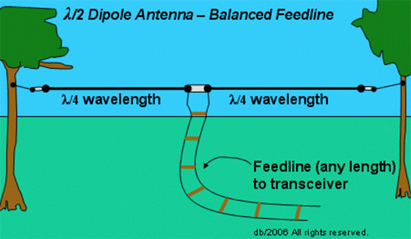 Figure 2: The dipole is usually attached to its supports via insulators (white) and wire lengths that allow the dipole arm lengths to be maintained independently of the distance between the supports. (Image source: Physics Forums)
In practice, the actual antenna length for optimal performance will likely need to be adjusted to accommodate the fact that the wire has a finite thickness and other deviations from theory but this adjustment is usually less than five percent. Even if not adjusted, performance is usually quite good, and the voltage standing wave ratio (VSWR) is usually below a generally acceptable 1.5:1.
In those cases where there is a significant antenna impedance shift or mismatch, the VSWR will rise to an unacceptable level, and performance will suffer. In such instances, an adjustable antenna tuner is used in the feedline to compensate and implement a transition.
The theoretical gain of the dipole is around 2 dBi (dB relative to isotropic). Its radiation pattern is simple and often characterized as a torus or donut (Figure 3).
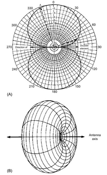 Figure 3: The radiation pattern for the dipole as viewed from above in the vertical plane (A), and from the side in the horizontal plane where it resembles a torus or donut (B). (Image source: Science Direct)
The user can adjust the antenna orientation to direct maximum transmitter energy/receiver sensitivity toward the intended radio transceiver, often located thousands of miles away. There are many documented cases of successful communication at these distances using a dipole at 20 and 40 m with transmit power well below a watt and under suitable atmospheric propagation conditions, as its efficiency and radiation pattern are that good.
Multiband operation extends versatility
In many real-world HF communication situations, it is necessary to try to establish a contact in more than one band at the same time or switch bands at different hours, since connectivity is a function of many variables such as sunspots, atmospheric noise, daytime versus nighttime operation, and constantly varying propagation conditions. As a result, a single-band dipole antenna may be insufficient.
The obvious solution is to set up multiple dipole antennas, one for each band/wavelength of interest. However, doing so has practical difficulties for rigging, tangling, managing, and switching between multiple feedlines. In some cases, an RF splitter/combiner could be used to enable a single feed line to connect to two antennas, but this introduces losses and new impedance matching issues.
Fortunately, there’s a better solution that, like the dipole, has been in use since the earliest days of wireless: the “trap.” (It’s unclear when this term was first introduced or by whom; the word is not used on the 1941 US Patent 2,229,865 that presents the technique.) A trap is a simple, parallel-connected inductor-capacitor (LC) combination which is self-resonant between two bands of interest.
One trap is inserted into each arm of the dipole to make the antenna have two electrical lengths but one physical length. At frequencies below the resonant frequency, the trap’s reactance will be inductive; above the resonant frequency, it will be capacitive. Traps act like a switch, electrically cutting off the rest of the antenna at the trap’s design frequency and functioning as a loading coil below the antenna’s resonant frequency.
A simplified electrical model of the trap shows the physical inductor and capacitor and a small parasitic resistance (RP) (Figure 4).
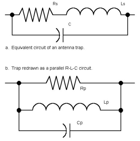 Figure 4: The trap is a simple resonant LC circuit with some undesired, unavoidable resistance which can be modeled in series (a), or as a parallel RLC circuit (b). (Image source: AntenTop)
Traps can have a reputation for being lossy, which would be a concern for both transmit and receive modes. However, a properly designed and tuned trap will impose a modest loss on the order of 1 dB, and that is usually acceptable in exchange for the convenience that it provides.
Selecting the trap component values
Mathematically, there are an infinite number of LC pairings that will result in a desired resonant frequency. However, many of these would require an extremely small (or large) inductor matched with an extremely large (or small) capacitor, respectively. Such a pairing would be excessively affected by parasitics and physical size issues, and also have a Q-factor (quality factor) that was too narrow or broad for the band of interest.
Fortunately, there is considerable literature available on sizing traps based on theory, implementation, and hands-on field experience. For example, a trap using a 5.55 microhenry (µH) inductor paired with a 100 picofarad (pF) capacitor is a good starting point for an 80/40 m dipole (Figure 5).
 Figure 5: The component values shown and the dipole linear dimensions (in feet) are a good starting point for an 80/40 m multiband dipole. (Image source: QSL Net)
Selecting trap components is about more than just determining suitable L and C values, as there are some very practical issues of power handling and ruggedness. For receive-only antennas, almost any inductor or capacitor can handle the very small amount of received power, which is on the order of milliwatts, and often less. However, transmitters often provide power levels ranging into the tens, hundreds, and even more watts, so the trap components must be rated for those power levels.
Traps are also exposed to the weather. While some dipole antennas are located in benign environments such as an attic or wooden barn, most are outside and thus must endure rain, wind stress, temperature extremes, condensation, and more. Therefore, the trap and its connection must be either completely sealed, have some sort of drainage and venting arrangement, or be constructed with weather-resistant materials. Even if the connections remain intact, any water intrusion or corrosion can affect component values and thus shift the resonant frequency.
Trap construction usually requires encapsulating its components by sealing them in a plastic case, using conformal coating, or using some sort of weather-resistant exposed construction (Figure 6). Low-cost PVC pipe is often used as the core of a wound inductor; in other cases, a PVC pipe with tight end caps is used as the enclosure with watertight access holes.
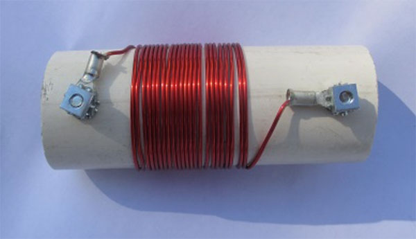 Figure 6: This homemade 80/40 m trap uses a hand-wound inductor around a PVC pipe as its core support. (Image source: www.vk4adc.com)
There’s another practical issue to consider: tuning and trimming the trap components. While calculating the component values is a necessary first step, these ideal values are often not quite close enough due to parasitics, wire diameter, and inductor winding imperfections, to cite but a few real-world factors.
For this reason, most homemade traps and many commercial ones allow the user to make some adjustments to the L and C values in the field to achieve the desired performance, which is usually done with a VSWR meter. This fine-tuning can be a frustrating, iterative process, especially with DIY implementations; again, there are many websites with practical suggestions for simplifying the process.
The use of traps is not limited to solely using a long-wire dipole over two bands. It is possible to build three and even four-band dipole antennas using a series of traps. However, doing this requires additional adjustments and some performance compromises and tradeoffs in antenna radiation pattern, gain, bandwidth, and other parameters.
Not limited to simple dipoles
While traps are usually associated with basic long-wire dipoles, they are not limited to that antenna design. For example, a multiband, directional, high-gain Yagi-Udi antenna (often simply called a “Yagi”) is constructed using an array of active and passive dipole elements. This form of Yagi uses traps in its director, active drive, and reflector elements so it can function across multiple bands (Figure 7).
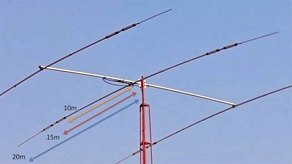 Figure 7: Traps can be used for three-band operation on basic dipoles as well as on more complex multiband antennas such as this 20/15/10 m Yagi design; shown (left to right) are the antenna director, driven, and reflector elements, each with two traps on each arm. (Image source: OnAllBands)
It is possible to build your own dipole, and many one-off users do just that. But they are also available as standard commercial units such as the KGI825 from PulseLarsen Antennas. This basic quarter-wavelength dipole with 2 dB gain is designed for operation from 806 to 896 megahertz (MHz), centered at 851 MHz (Figure 8).
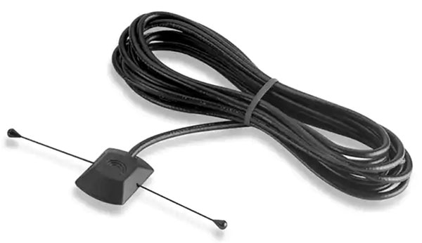 Figure 8: The KGI825 is a quarter-wavelength dipole antenna with 2 dB gain and a center frequency of 851 MHz. (Image source: PulseLarsen Antennas)
The KGI825 can handle up to 60 watts of transmit power and offers convenient magnetic mounting inside a window between 0.138 and 0.158 inches thick (3.5 to 4 millimeters). It comes with a 14 foot (4.25 m) RG-58/U coaxial cable to which the user adds the desired connector.
Conclusion
The humble, modest, low-tech, long-wire dipole antenna has served the wireless world for over a century. It continues to do so due to its simplicity, adaptability, portability, and effectiveness. By using passive traps, its ability to function can be extended across two or even more bands in the high-frequency part of the electromagnetic spectrum.
Related Content
“Understanding Antenna Specifications and Operation, Part 1”
https://www.digikey.com/en/articles/understanding-antenna-specifications-and-operation
“Understanding Antenna Specifications and Operation, Part 2” https://www.digikey.com/en/articles/understanding-antenna-specifications-and-operation-part-2
“Antennas: Design, Application, and Performance”
https://www.digikey.com/en/articles/antennas-design-application-and-performance
“The Use of Baluns for Measurements”
https://www.digikey.com/en/articles/the-use-of-baluns-for-measurements
“Understanding the RF Balun and its Transformative Function”
https://www.digikey.com/en/articles/understanding-the-rf-balun-and-its-transformative-function
“Use PIFAs to Solve the Small-Product, Smaller-Antenna Dilemma”
https://www.digikey.com/en/blog/use-pifas-to-solve-the-small-product-smaller-antenna-dilemma
External References
- H.K. Morgan, U.S. Patent 2,229,865, “Radio Antenna System”
- MicrowaveTools, “Dipole Antenna”
- Science Direct, “Antenna Fundamentals: Radiation Pattern”
- On All Bands, “Antenna Traps—A Way to Cope With Limited Space ”
- QSL Net, “Tuned Circuits and Traps”
- AntenTop, “Modeling Trap Antennas”
- AntenTop, “Multirange Trap Antennas”
- VK4ADC's web, “Low Cost Antenna Traps”
- SOTABeams, “Using Antenna Traps”

Have questions or comments? Continue the conversation on TechForum, DigiKey's online community and technical resource.
Visit TechForum


