An Introduction to EMI and EMC Measurement of Power Supplies—Part 2: Radiated EMI
Part 1 of this blog series dealt primarily with measuring conducted electromagnetic interference (EMI). Here, Part 2 discusses the measurement of radiated EMI.
Radiated EMI is undesired electromagnetic energy that is transmitted into free space, as transverse electromagnetic waves or via capacitive or inductive coupling. Circuit board conductors carrying signals that vary in time radiate electromagnetic energy into space. Every circuit board trace is a veritable antenna capable of transmitting or receiving signals. Switched-mode power supplies with large switching voltages and currents, if not properly designed, are prone to create EMI (Figure 1).
 Figure 1: The signals encountered in a switched-mode power supply include broadband voltage and current waveforms with high slew rates, as well as narrowband signals like those associated with the switching frequency and oscillatory signals such as ringing. (Image source: Art Pini)
Radiated EMI testing requires measuring the electromagnetic field strength of the EMI signals generated by the device under test (DUT) that are inherent in the high-slew-rate switching voltages and currents.
Radiated EMI compliance testing is performed in an anechoic shield room that isolates signals from the DUT (Figure 2). The sensing antenna is kept at a specified distance—typically one meter—from the DUT. Biconical and log periodic antennas are commonly employed.
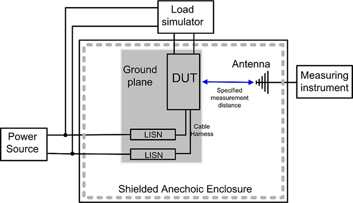 Figure 2: Radiated EMI compliance testing takes place in a shielded anechoic room where the DUT is isolated from external RF radiation. (Image source: Art Pini)
The DUT is located on a table above a ground plane. These particular emissions tend to be directional, so the DUT is on a turntable to provide a sensing antenna with a good line-of-sight aspect. The antenna is also moveable and has an adjustable height. During testing, the orientation producing the highest measured response is noted and used as the basis for the compliance test. The cabling to the DUT is part of the test and is enclosed in a cable harness.
The test lab will scan the frequency band of interest using a spectrum analyzer or EMI receiver and look for emissions that are close to the test limits. It does this for all DUT orientations and antenna polarizations. The test lab focuses on each of these emissions and quantifies the amplitude of the field strength.
The results of a typical radiation emissions test on a Texas Instruments LM61495Q3RPHRQ1 10 ampere (A) automotive buck converter is shown in Figure 3.
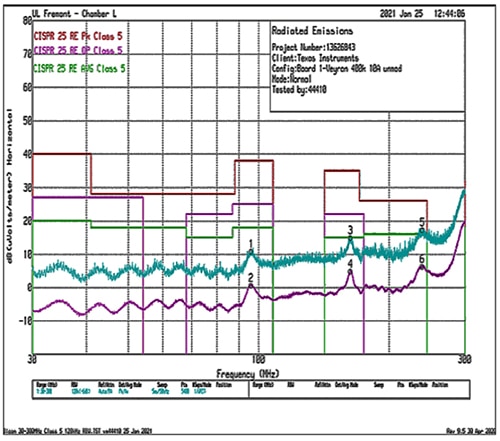 Figure 3: Shown is the typical radiated emissions test under CISPR 25 Class 5 for the LM61495Q3RPHRQ1 10 A buck converter. Test limits for peak, quasi-peak, and average detector response are plotted. Acquired data for peak (blue) and averaged (violet) measurement responses are shown. (Image source: Texas Instruments)
The specification has test limits for peak, quasi-peak, and average detector responses. The quasi-peak response is a processed response that weights amplitude peaks by the frequency of occurrence. The peak and average measured responses are plotted. Each must have amplitudes below the appropriate test limit in order to be in compliance.
Since compliance testing is a costly and time-consuming process, most designers engage in pre-compliance testing outside of the shielded room using near-field measurements. Near-field measurements are made within a foot (30.5 centimeters (cm)) of the DUT using near-field probes, such as Teledyne LeCroy’s T3NFP3 kit. Near-field probes sense either electric or magnetic fields (Figure 4). Also, near-field probes, unlike most probes, are not calibrated and are used for relative measurements and for locating emission sources.
 Figure 4: The Teledyne LeCroy T3NFP3 near-field probe kit contains three magnetic probes and one electric field probe. (Image source: Teledyne LeCroy)
The T3NFP3 near-field probe kit consists of three magnetic probes and one electric field probe. These probes act as wide-bandwidth antennas sensing radiated emissions in the range of 300 kilohertz (kHz) to 3 gigahertz (GHz). The magnetic probes use a loop structure and are available in diameters of 20, 10, and 5 millimeters (mm). The larger loops have greater sensitivity and are ideal for discovering radiated signals. The smaller loops are less sensitive but are more geometrically precise to help find the source of the radiation. The probe sensitivity is at a maximum if the magnetic field is at a right angle to the plane of the loop. This angular sensitivity is used to determine the direction to the source.
The electric field probe is a monopole antenna, and it is important to orient this probe perpendicular to the plane of the measurement. The electric field probe helps identify high voltage sources, as well as unterminated sources.
The B&K Precision PR262 is similar to the T3NFP3 but adds a 40 dB pre-amplifier for detecting very low-level signals (Figure 5). It covers a frequency range from 9 kHz to 3.2 GHz.
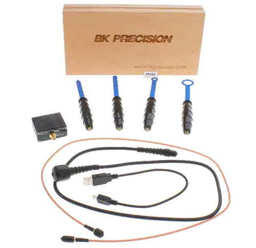 Figure 5: The PR262 set is similar to the T3NFP3, but adds a 40 dB pre-amplifier to detect very-low-level signals. (Image source: B&K precision)
The output of the near-field probe is connected to the 50 Ohm input of the measuring instrument. The probe head, which is insulated, is passed over the PC board while monitoring the response for the indication of a radiated source. Both magnetic and electric field probes are used to verify the source of the radiated EMI signal.
Conclusion
With every trace on a circuit board a veritable antenna radiating EMI, it’s critical to perform pre-compliance testing using near-field probes such as the T3NFP3 and PR262. These can help to quickly detect and isolate the source of EMI so it can be mitigated before proceeding to formal—and expensive—compliance testing.

Have questions or comments? Continue the conversation on TechForum, DigiKey's online community and technical resource.
Visit TechForum


