An Introduction to EMI and EMC Measurement of Power Supplies - Part 1: Conducted EMI
Electronic devices are involved in almost every aspect of life, and the proliferation of these devices leads to the question of how much do they interfere with each other? Electromagnetic compatibility (EMC) and electromagnetic interference (EMI) are metrics we use to determine how well electronic devices and systems play together.
EMI measurements quantify how well a device limits interference with other devices or systems. The converse of this is EMC measurements, which quantify how external systems impact the operation of an electronic device being tested.
There are a large number of national and international standards that have been established to minimize interference and to assure the compatibility of all electronic devices and systems. These standards organizations include Comité International Spécial des Perturbations Radio (CISPR), International Electrotechnical Commission (IEC), International Organization for Standardization (ISO), Society of Automotive Engineers (SAE), Federal Communications Commission (FCC), and several others.
Acceptance testing of electronics is a rite of passage for all manufacturers, and designers should be aware of the types of testing and the specification limits before beginning any design. Likewise, development engineers and technicians should be able to perform pre-compliance testing to minimize unexpected delays in product acceptance and introduction.
Power supply design from the point of view of EMI offers many challenges to the design engineer. Interference can propagate from the supply via radiation through the air (radiated interference) or be conducted through the device’s wiring (conducted interference). Test standards have measurements for both types of interference. The balance of this post will deal with conducted EMI.
Conducted EMI testing
Conducted interference from a power supply arises from the discontinuous current flow within a switched-mode power device. Conducted interference is broken down into two components: common mode and differential signals (Figure 1). Note that common-mode signals travel in the same direction in the lines between the power source and the device under test (DUT), a power supply, in this case. The ground line provides the necessary return path. Differential signals travel in opposing directions.
 Figure 1: Conducted EMI is composed of common mode and differential components based on the direction of signal flow between the DUT and the power source. (Image source: Art Pini)
Testing conducted emissions requires the use of a line impedance stabilization network (LISN) installed between the power source and the DUT (Figure 2).
 Figure 2: An example of an LISN placed between the power source (line, L, and neutral, N) and the power supply being tested. (Image source: Texas Instruments)
The LISN is basically a low-pass filter inserted in series with the power source. Its purpose is to assure a stable, known source impedance over the frequency range being tested. It also provides isolation between the power source and the DUT and measuring equipment from the input power source. Note that it also provides a connection for the measuring instruments, normally a spectrum analyzer or EMI receiver, at safe amplitude levels.
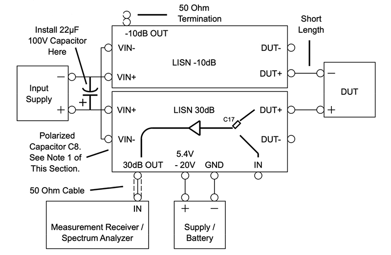
The Analog Devices DC2130A spectrum analyzer power management board is a dual LISN. One section of the evaluation board provides 10 decibels (dB) of attenuation over a frequency range of up to 800 megahertz (MHz) for the measurement port. The other section provides 30 dB of gain to amplify small EMI signals over a frequency range of from 10 MHz to 2.5 gigahertz (GHz). Each section can be used independently, or they can be combined (Figure 3).
 Figure 3: The setup of the DC2130A using the -10 dB and +30 dB LISNs for common-mode isolation. The power supply/battery provides power for the +30 dB amplifier. (Image source: Analog Devices)
Mitigating conducted EMI on an existing design usually involves adding an EMI filter between the power source and the power input to the DUT. The latest designs for DC-DC converters have included onboard active EMI filters, which provide superior EMI reduction in a smaller physical area than discrete component filters.
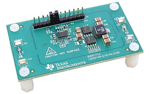
An example of one such active filter is incorporated into the Texas Instruments LM25149-Q1EVM-2100 evaluation board (Figure 4). This board uses the LM25149-QI synchronous buck converter with an active EMI filter. The converter also features spread-spectrum modulation, which frequency modulates the switching clock to distribute any EMI over a range of frequencies, thereby reducing peak amplitudes.
 Figure 4: The LM25149-Q1EVM-2100 evaluation board uses an active EMI filter, as well as spread spectrum modulation. The latter spreads EMI across a range of frequencies to reduce peak amplitudes. (Image source: Texas Instruments)
For this evaluation board, the effectiveness of these techniques can be seen in a CISPR 25 Class 5 conducted emissions test comparing the conducted EMI with no mitigation feature enabled to operate with both the active EMI filter and spread spectrum switching (Figure 5). The tests use spectrum plots of EMI amplitude in dB versus frequency.
 Figure 5: CISPR 25 Class 5 conducted emissions plots comparing the EMI levels between operations with no EMI mitigation (a), to EMI levels with the active EMI filter and spread spectrum enabled (b). (Image source: Texas Instruments)
The red horizontal lines mark the peak and average test levels for conducted EMI for CISPR 25 Class 5 certification. The measured peak spectrum, shown in yellow—without mitigation—is about equal to the peak test limit at the switching frequency of 2.1 MHz, exceeding the average test limit. With EMI filtering and spread-spectrum switching, both peaks are well below the test limits.
Conclusion
The ubiquity of electronic devices make EMI and EMC testing and mitigation increasingly important, but it’s a complex art. However, there are some basic principles. As shown, the testing of conducted EMI requires a power source, LISNs, and a spectrum analyzer or EMI receiver. Part 2 of this series will discuss radiated EMI testing.

Have questions or comments? Continue the conversation on TechForum, DigiKey's online community and technical resource.
Visit TechForum


