For PC Board Power Distribution Topologies, the “Optimum” Solution Boils Down to Experience
Engineers are routinely expected to analyze, create, and deliver the “best” or “optimum” solution to a given problem. While it is possible to do so in some design situations, it certainly isn’t the case for all. The reason is simple: against which parameters and their values do you judge what is best? Is there one critical, overwhelming factor, or is it a subtle balance among the many different factors that is somehow magically optimized?
Face it: engineering design is not only about expertise in the execution of the design itself, but also in working through the many tradeoffs and compromises that each design requires. It can be very frustrating when people who were not in the design loop casually critique prior decisions by asking, “Why didn’t you do such-and such?” Or, “Couldn’t you simply have added ‘x’?” These are easy-to-ask questions when you are distant from insight into the tradeoffs that were made.
For some applications, of course, one or two performance requirements may dominate the list, such as the need for low power consumption and long-term reliability for a deep-space mission. For other cases, it’s essential to meet some specifications, but there is no need to exceed them since the end product won’t benefit from any excess.
In all designs, though, engineers obviously must try to assess the nature and degree of linkages among the various project objectives. For example, if a little more power dissipation significantly boosts speed or enhances accuracy, that may be a very good tradeoff. But how do you quantify the “cost” versus “benefit”? You can’t reliably do that in many cases, and even if you could, that relationship is usually valid only over a very small range. The relationship links become even more complex, subtle, and hard to define as the number of such variables increases.
So, what about the power distribution topology?
To illustrate the complexity of the optimized solution challenge, let’s look at a well-defined system function: the power distribution topology (PDT). Every electronic design has a power subsystem, but we’ll focus on a smaller and bounded one of power on a single pc board. Usually this involves several voltage rail values and different current demands of any individual rail, but we can start with a simple case of two identical 5 volt loads of 0.9 amperes (A) each.
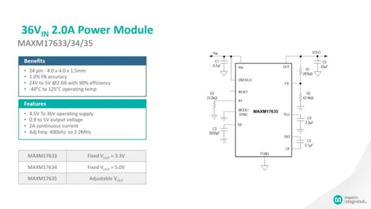
Even for this very simple situation, there are two distinct options (Figure 1) that can be implemented using DC-DC step-down modules such as those in Maxim Integrated’s uSLIC Himalaya family. One option is to use two Maxim MAXM17632 5 volt/1 A units with one for each load, while a second option is to use a single Maxim MAXM17635 5 volt/2 A module to supply both loads. Further, what if one of the loads is just 75 milliamperes (mA) rather than 900 mA: do you use the 2 A unit to supply both, or use a 1 A MAXM17632 plus a smaller, 5 volt/100 mA MAXM17900 for the second? As usual, the answer is easy: “it depends.”
 Figure 1: There are two topologies that can deliver power at the same voltage to two independent loads: use two smaller DC-DC modules (top), or a single larger module common to both (bottom). (Image source: DigiKey)
Either approach should work, but consideration needs to be given to factors such as the location of the loads relative to each other, overall efficiency versus load, overall dissipation if either load has quiescent periods, and noise pickup from pc board trace routing. Even footprint is a factor: the 2 A module is 4 x 4 millimeters (mm) = 16 mm2, while the 1 A units are 3 x 3 mm each for a total 9 + 9 = 18 mm2 footprint. That extra 2 mm2 may seem of little consequence, but it may make a big difference in a tight design; analytically, it’s a footprint increase of 12.5%.
And it gets harder
For such a simple A vs B scenario, it’s likely that one option will be better, even if not by a wide margin. However, for the more complicated cases having many loads, even at the same nominal voltage, there are often many hard and soft factors to consider such as:
- Number of loads
- Typical, maximum, and quiescent current for each
- Location of loads with respect to each other
- Dynamics of each load
- Noise pickup due to longer traces between power module and load
- Accuracy and regulation of voltage at load—one load may need ±0.5% while another needs 1%
- Load balancing: what if one load needs 2 A and another needs only 50 mA—would a low-dropout (LDO) regulator for the 50 mA load be a smarter move?
- Virtues of close-in point-of-load (PoL) power conversion and required bypassing
- Pc board area needed for running unregulated primary DC power as well as multiple regulated DC power traces (and their grounds); impact on layout flexibility
- Aggregate footprint of power modules and their support components
- Location flexibility on PC board
- Clock frequencies, EMI and “beat” issues; use of a common clock versus individual DC-DC clocks
- Overall efficiency of the various regulator configurations
- Number and type of needed passive components
- Current-resistor (IR) drop, trace width, and possible need for remote sensing at higher current levels
- BOM component cost
This list illustrates the multifaceted complexity of the problem. Even for the simple case of a single voltage, the number of possibilities and the related degrees of freedom increase dramatically as the number and characteristics of the loads increases.
Solving the problem is not a matter of doing an exhaustive search through all of the possibilities. EDA software can analyze a given approach and grade it against the objectives, and even help by looking at modest “what if” changes to each, but it can’t envision the various possibilities and assess the benefit versus cost and tradeoffs of a given topology (at least not yet; perhaps with artificial intelligence (AI) it will do so in a few years!). Add to this the reality of needing multiple rail voltages, and the problem becomes far more complex, especially as you can have different intermediate bus conversion stages.
That’s why I have seen engineers use basic spreadsheets rather than EDA tools to score the impact of the many topology paths. In the end, however, many of the spreadsheet cells get filled in with qualitative assessments such as “poor”, “good”, or “very good”, plus little notes appended to each cell such as “good--but only up to 2 A”.
It would be nice if it were possible to create solid equations linking the many variables in the analysis of power distribution topologies. This won’t happen soon, as there are so many interrelated degrees of freedom, but they are linked by nonlinear correlations, inflection points, saturation points, and other complex and usually hard-to-quantify correlations.
That’s where engineering expertise, experience, judgement, and even intuition come into the picture when deciding on the preferred PDT approaches. Determining the “best” power topology for even a single pc board is a true example of what engineering is about and takes more than a dispassionate numerical analysis.
Conclusion
When someone says they have the optimum solution to the design problem, the logical question to ask is simple and direct: “Optimum with respect to which parameters, and to what extent?” Even something as basic and tangible as your PDT has a large list of critical factors, with some closely linked and others loosely linked.
If you are presenting your PDT solution at a design review, you will undoubtedly be asked by fellow engineers how and why you selected your proposed topology. Be prepared to thoughtfully present your analysis, explain your thinking, and acknowledge where experience and judgement were used rather than numbers alone. By doing so, you should be able to make clear why your combination of DC-DC power modules and associated components is clearly an appropriate choice, but not the only one.
Recommended Reading:
Maximize Gains Using Miniaturized PoL Converters
https://www.digikey.com/en/articles/maximize-gains-using-miniaturized-pol-converters
When More is Less: Save Valuable Space Using More Regulators
https://www.digikey.com/en/articles/when-more-is-less-save-valuable-space-using-more-regulators
Common Mistakes to Avoid When Using Midrange Current DC/DC Regulator Modules
Advantages of Modular DC/DC Converters Over Discrete Solutions
https://www.digikey.com/en/articles/advantages-modular-dc-dc-converters-over-discrete-solutions
Power Supply and Topology Solutions for Driving LED Arrays
https://www.digikey.com/en/articles/advantages-modular-dc-dc-converters-over-discrete-solutions
About this author

Bill Schweber is an electronics engineer who has written three textbooks on electronic communications systems, as well as hundreds of technical articles, opinion columns, and product features. In past roles, he worked as a technical web-site manager for multiple topic-specific sites for EE Times, as well as both the Executive Editor and Analog Editor at EDN.
At Analog Devices, Inc. (a leading vendor of analog and mixed-signal ICs), Bill was in marketing communications (public relations); as a result, he has been on both sides of the technical PR function, presenting company products, stories, and messages to the media and also as the recipient of these.
Prior to the MarCom role at Analog, Bill was associate editor of their respected technical journal, and also worked in their product marketing and applications engineering groups. Before those roles, Bill was at Instron Corp., doing hands-on analog- and power-circuit design and systems integration for materials-testing machine controls.
He has an MSEE (Univ. of Mass) and BSEE (Columbia Univ.), is a Registered Professional Engineer, and holds an Advanced Class amateur radio license. Bill has also planned, written, and presented on-line courses on a variety of engineering topics, including MOSFET basics, ADC selection, and driving LEDs.

Have questions or comments? Continue the conversation on TechForum, DigiKey's online community and technical resource.
Visit TechForumRelated Blogs


More Blogs from this Author