Tiny Step-Down Power Modules Simplify Designers’ ‘Make or Buy?’ Choice
Contributed By DigiKey's North American Editors
2020-08-11
Electronic devices are pervasive and embedded everywhere, from the Internet of Things (IoT), medical clinical devices and wearables, to smart buildings, intelligent sensors, and myriad consumer products. Whether their primary source of power is a line-operated AC-DC converter or a battery, the challenge is to provide these devices with one or more low-voltage, properly regulated, well-behaved DC power rails. In addition to the primary function of delivering tight regulation—while often working from a wide input voltage range—the step-down DC-DC subsystem in these devices must be small, efficient, electrically quiet, and meet strict regulatory requirements.
Designers have two clear options to provide this DC power: They can design and build (“make”) their own DC-DC subsystem, or they can elect to buy a module off the shelf that is complete and ready to use. “Making” has its advantages in terms of customization but can add to cost and delays as power supply design combines technology, craft, art, and some luck. Until recently, the “make versus buy” threshold was such that it made technical and cost sense to buy for high-range (>100 watts (W)) and mid-range supplies (>~10 W to <~ 100 W), while at the low end (<~10 W) it was often a “make” decision. Designers could craft their own step-down unit using a low-dropout (LDO) or switching regulator IC, plus a few external passive components.
Now, however, due a combination of increasingly challenging time-to-market requirements, combined with innovations in the direction of tiny, complete modules, the buy decision is much more attractive and sensible, even at the lower power levels.
This article looks at the key parameters, performance requirements, and solutions related to lower DC-DC power delivery, using by way of example the Himalaya uSLIC step-down DC-DC power module family from Maxim Integrated.
Basic performance is just the start
As with other power sources, low-power step-down DC-DC regulators are initially characterized by a few basic parameters: input voltage range, output voltage setting (fixed or adjustable), and maximum output current. These are the starting parameters. There are additional factors related to the quality, including regulation and stability under varying loads, ripple current, and transient performance. There are also valuable features such as undervoltage lockout (UVLO), short-circuit and thermal protection, overvoltage protection (OVP), and overcurrent protection (OCP).
The list of important parameters also includes operating efficiency. In some cases, high efficiency is required to meet regulatory “green” mandates, although these regulations are not as stringent for lower power sources as they are for the middle and higher range sources. Higher efficiency also helps extend run time in battery-powered applications and is important under nominal load and low load conditions, as well as in quiescent mode. Even when there is an AC line as the primary source and runtime is not determined by efficiency, it is still critical to minimize energy dissipation and thermal load.
Electromagnetic interference (EMI) considerations are also a regulatory-driven factor in two ways:
- First, DC-DC regulators must not be susceptible to “incoming” EMI and noise, as this would affect their performance and whatever they are powering.
- They must not be sources of radiated and conducted EMI, with the allowable EMI limits being a function of end application (e.g., consumer, automotive, industrial, and medical), power range, and frequency.
Getting a product certified to meet the various EMI mandates is a complicated and time-consuming process requiring both design and test expertise.
No discussion of the demands placed on the power regulator functions can ignore two other factors: size and cost. Generally, smaller is better and often required, although that may not be a top priority for products with larger form factors. Lower cost is always welcome, of course, though its relative importance is determined by the application requirements.
‘Make vs buy’ gets new assessment criteria
There are clearly trade-offs between the make versus buy decision, including the relative weightings of the underlying factors. For example, how much is a smaller solution worth? How much for better performance along one axis? For example, a 2 megahertz (MHz) switching regulator is smaller than the 1 MHz version with comparable basic specifications, but its efficiency is likely lower due to increased losses operating at the higher frequency.
Given the many apparently easy-to-use, high-performance DC-DC regulator ICs that are available for lower power levels, it may seem that “make” is a sensible decision. However, the reality is that this increasingly is not the case. This is due to an accumulation of factors, including the many demands placed on the circuit’s performance and the risks associated with “make”, including getting it into production, the challenges with sourcing the associated passive devices, and stringent test/certification demands.
An inductor clarifies the situation
Switching regulators require a small inductor for energy storage which cannot be fabricated on-chip. In principle, an inductor is an almost trivial component and its initial model is characterized simply by its inductance and DC resistance. Once the designer has the values for these two factors, the modeling and design of the DC-DC regulator can proceed, in theory.
In practice, things are not so simple, and even a simplified “improved” model of an inductor incorporates self-capacitance as a function of frequency (Figure 1).
 Figure 1: Even the simple inductor’s equivalent circuit has some complexities, and its model changes with frequency of inductor operation. (Image source: Springer Nature Switzerland AG)
There is no single “right” model, and advanced, highly detailed models include additional hard-to-assess parasitic elements (Figure 2).
 Figure 2: As the frequency at which the inductor is being used increases, the equivalent circuit develops many more subtleties, with some being a function of inductor placement, neighboring components, and the pc board. (Image source: Sonnet Software, Inc.)
The physical size and placement of the inductor complicates that model; and even a slight shift in its position or orientation changes the accuracy of the model and affects performance, EMI, and efficiency. As switching frequencies extend into the megahertz range, the models must increasingly capture these additional factors.
Additionally, there’s an issue to which experienced engineers can attest: sometimes purchasing departments or production facilities substitute a similar part in place of the specific vendor and model the engineer has called out on the bill of materials (BOM). This “innocent” substitution seems like it will be a non-issue since the top-tier specifications of the different units are identical. However, the subtler second-tier specifications of the component may differ such that the DC-DC regulator performance changes from what was built, tested, and approved to one that does not work as tested and released.
For these and other reasons, the do-it-yourself “make” path using one of the many available regulator ICs and a few passive components is increasingly risky with respect to performance, compliance, and time to market. It adds up to making “buy” look very attractive using viable alternatives.
Balance tips strongly toward ‘buy’
The buy landscape at this lower power range has shifted dramatically in the past few years. Designers can now select among a wide choice of devices in the Himalaya uSLIC step-down DC-DC power module family from Maxim Integrated. These modules do not have the trade-offs or compromises in performance and size, or risk of the “make” decision.
The Himalaya uSLIC family includes two fixed output units, the MAXM17630 (3.3 volt output) and the MAXM17631 (5 volt output), as well as the resistor-set, adjustable MAXM17632 (0.9 volt to 12 volt output)—all with 1 ampere (A) current capability. Each of these synchronous step-down DC-DC modules includes an integrated controller, MOSFETs, compensation components, and inductor. The built-in compensation across the output voltage range eliminates the need for external compensation components, which are often difficult to select as they must be matched to the regulators’ operating modes.
The modules operate over a wide input range from 4.5 volts to 36 volts; other uSLIC modules are available for operation from inputs as high as 60 volts, which is useful for industrial designs. The feedback voltage regulation accuracy for the module family is ±1.2%. The modules include overtemperature protection and are specified for -40°C to +125°C ambient operating temperature.
These modules need only a few non-critical external resistors and low-cost ceramic capacitors to function and establish operating characteristics (Figure 3).
 Figure 3: The MAXM17631 is a member of the Maxim Himalaya uSLIC family of DC-DC step-down power modules that are easy to configure and use; note the lack of a visible inductor. (Image source: Maxim Integrated)
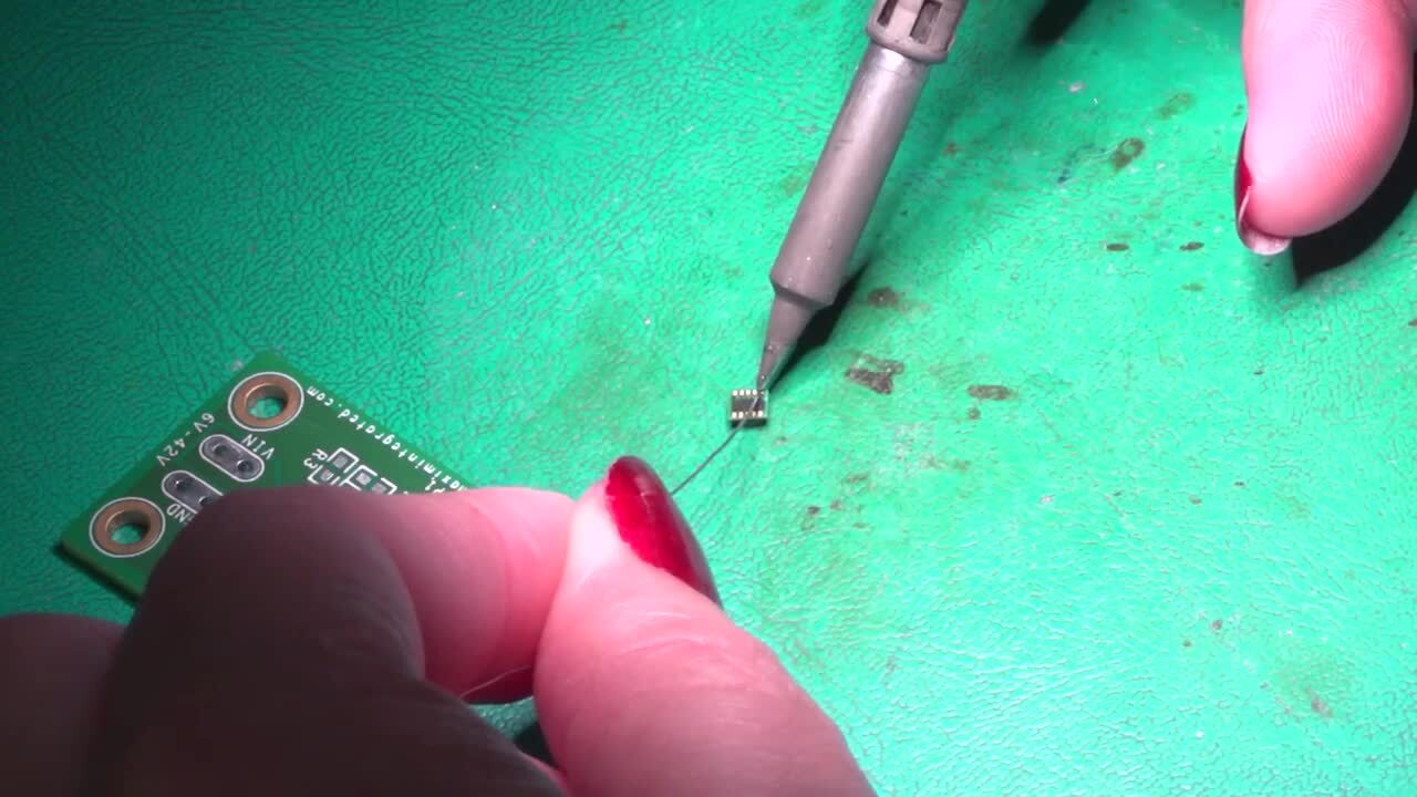
They are “hardware-only” with no software initiation or set-up port to consider. Although they are not ICs, they do look like them. The internal inductor is encapsulated within the tiny, low-profile, 16-pin, 3 millimeter (mm) × 3 mm 1.75 mm package, with an integral bottom-side thermal pad (Figure 4).
 Figure 4: The members of the Maxim Himalaya uSLIC family measure just 3 mm × 3 mm × 1.75 mm with 16 pins; the packages also have an underside thermal pad to simplify heat sinking. (Image source: Maxim Integrated)
Despite their small size, the Himalaya uSLIC modules offer high performance, ease of use, and flexibility in configuration. They support adjustable frequency operation from 400 kilohertz (kHz) to 2.2 MHz with the option of external clock synchronization. Further, there is no need to worry about the power module being a reason to fail to meet stringent EMI mandates, as the units comply with CISPR 22 (EN 55022) Class B Conducted and Radiated Emissions requirements (Figure 5 and Figure 6).
 Figure 5: The members of the Maxim Himalaya uSLIC family easily meet the CISPR 22 (EN 55022) Class B conducted emissions limit allowance. (Image source: Maxim Integrated)
 Figure 6: The members of the Maxim Himalaya uSLIC family also fall below the CISPR 22 (EN 55022) Class B allowance for radiated emissions. (Image source: Maxim Integrated)
They also meet JESD22-B103, B104, and B111 Pass Drop, Shock, and Vibration Standards; doing so in a “make” design is an additional burden beyond meeting the electrical performance requirements.
Why not use an LDO instead?
Low dropout regulators (LDOs) are widely used in the countless millions every year and satisfy the needs of many applications. They are easy to apply and present virtually no output noise. However, their efficiency decreases as the current they supply increases, and as the voltage differential between their supply rail and their output increases. In many lower power applications, they may appear to be a reasonably attractive solution to providing a regulated output despite the efficiency penalty.
However, this is often not the case. Consider the example of a space-constrained optical proximity sensor that requires 5 volts at 80 milliamperes (mA) from a nominal 24 volt DC supply (i.e., 19.2 volts DC to 30 volts DC) (Figure 7).
 Figure 7: A tiny uSLIC module can be used to effectively deliver the 5 volts at 80 mA required in this example of a compact optically based proximity sensor design. (Image source: Maxim Integrated)
A summary of a comparative analysis using a standard LDO versus the MAXM17532 uSLIC power module—a 0.9 to 5.5 volt output, 100 mA device—shows the dramatic difference (Table 1).
|
Table 1: The power saved when using a uSLIC compared to an LDO is dramatic, as is the difference in overall dissipation, which is about 5% of the amount when using the LDO solution. (Image source: Maxim Integrated)
The uSLIC power solution is four times more efficient than the LDO and reduces the power dissipation to 1/19 (down to about 5%) of the LDO solution with the nominal 24 volt input; the difference is even greater when the DC input is at its 30 volt value (the details of this analysis plus other examples are in Reference 1).
Complete but still configurable
Even though the uSLIC devices are “sealed” modules implementing a peak current-mode control architecture, the user has the opportunity to select one of three operating modes for them. This enables the choice of performance attributes that best match the application priorities and trade-offs and does not have to be selected when the parts are ordered; instead, it is done by the designer as needed via appropriate connection of a package pin. Thus, the same device can be used in its different modes across multiple products and even within the same product, simplifying the BOM and allowing for changes later in the design cycle.
The three modes are:
• Pulse width modulation (PWM) mode: The internal inductor current is allowed to go negative. This mode of operation is useful in frequency sensitive applications and provides fixed switching frequency operation at all loads. However, it gives lower efficiency at light loads compared to the other two modes.
• Pulse frequency modulation (PFM) mode: This mode disables negative output current in the inductor, providing higher efficiency at light loads because of lower quiescent current drawn from the supply. The disadvantage is that the output voltage ripple is higher compared to the other modes of operation, and the switching frequency is not constant at light loads.
• Discontinuous conduction mode (DCM): This mode also enables high efficiency under light load conditions and includes constant frequency operation down to lighter loads than PFM mode by disabling negative inductor current at light loads. It offers efficiency that is between PWM and PFM modes, and the output voltage ripple in DCM mode is comparable to PWM mode and relatively lower compared to PFM mode.
For these uSLIC modules, users can also set factors such as the start-up time by using an external optional capacitor. This feature is useful in multi-rail designs where power sequencing and ramp-up rates are critical.
Modules eliminate characterization effort
One of the many tasks facing engineers who choose the “make” option is to properly evaluate their end product under various static and dynamic operating conditions, and across many different parameters. This is a time-consuming effort and also one with many opportunities for unintentional mistakes. Among the many requirements is that the load must be carefully and actively controlled.
In contrast, the design team can skip this step when using the Maxim Himalaya uSLIC modules. Since the units are complete, they are fully characterized from input pins to output rails on their data sheets. In addition to tables of electrical characteristics, there are over one hundred graphs defining performance, covering factors such as efficiency versus load current, output voltage versus load current, output voltage ripple, load transient response, start-up and shut-down performance, and Bode plots, all across a wide range of operating conditions including always-important temperature. Additionally, powerful design and simulation tools are available that ease incorporation of a module’s behavior into a larger system-wide simulation.
Getting to hands-on quickly
Although the Maxim uSLIC modules are easy to apply and come with fully characterized performance as well as simulation models, designers may still have the need to get some “hands-on” feel for their capabilities and develop a comfort factor with these tiny devices. Since the uSLICs are so small, Maxim offers the MAXM17630EVKIT# evaluation board to accelerate assessment (Figure 8). This board has three adjacent independent sections, one each for the MAXM17630, MAXM17631, and MAXM17632 modules.
 Figure 8: The Maxim MAXM17630EVKIT# evaluation board provides direct support for configuration and assessment of the MAXM17630, MAXM17631, and MAXM17632 trio of modules, via three adjacent and independent sections. (Image source: Maxim Integrated)
It allows the user to exercise and assess uSLIC operation in any one of the basic modes of operation (PWM, PFM, and DCM), synchronize to an external clock if desired, enable and disable a module, and change UVLO settings. In initial set-up, the evaluation board configures the MAXM17630 module (3.3 volt @ 1 A) to operate at a 900 kHz switching frequency, over a 4.5 to 36 volt input range; the MAXM17631 module (5 volt @ 1 A) is configured to operate at a 1.250 MHz switching frequency over a 7 to 36 volt input range; and the MAXM17632 adjustable module is set for 13 volt @ 1 A operation at a 2.150 MHz switching frequency over a 20 to 36 volt input range.
The evaluation board schematic along with top and bottom board layout and mask are detailed in the data sheet. All that is required to use the evaluation board are a single 0 to 36 volt DC @ 1 A power supply, a digital multimeter, and load resistors that can sink up to 1 A at 3.3 volts, 5 volts, and 12 volts. The kit’s pc board layouts are also designed to limit radiated emissions from switching nodes of the power converter, resulting in radiated emissions below CISPR22 Class B limits.
The board also recognizes that an evaluation arrangement is not the same as the final design-in configuration. For this reason, it has provision for optional electrolytic capacitors that dampen input voltage peaks and oscillations that can occur during hot plug-in or are due to long input cables that are often part of the evaluation set-up but will not be present in actual use. These cables run between the input power source and the kit’s circuitry and can induce input voltage oscillations due to their inductance. The equivalent series resistance (ESR) of the electrolytic capacitor helps damp out the oscillations they may cause.
Conclusion
The Maxim Himalaya uSLIC modules clearly demonstrate that the “make versus buy” balance now strongly favors buy, even at relatively low DC-DC step-down converter power levels. Their small size, fully characterized performance, compliance with EMI and efficiency regulatory mandates, and simplification of the end-product BOM makes selecting them a logical decision.
References:
Disclaimer: The opinions, beliefs, and viewpoints expressed by the various authors and/or forum participants on this website do not necessarily reflect the opinions, beliefs, and viewpoints of DigiKey or official policies of DigiKey.