Mfr Part # 6160
SPARKLE MOTION MINI ESP32
Adafruit Industries LLC
License: See Original Project 3D Printing LED Matrix
Courtesy of Adafruit
Guide by Ruiz Brothers
Overview
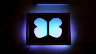
Make a nighttime display in the sky with an LED Matrix attached to a drone.
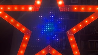
Powered by a Mini Sparkle Motion board and DJI Mavic Pro, this 1x1 meter 20x20 NeoPixel LED netting can display custom animated GIFs!
The 3D printed mounts allows the drone carry and power this matrix display without any modifications to the hardware.
3D print the parts in TPU filament. The printed legs extend the height of the drone for clearance, while the TPU clips on the arms hold the nylon line attached to a stake holding the matrix net.
The Mini Sparkle Motion board runs WLED to display complex animations.
With the PixelMagic Tool, we can build custom animated GIFs to run as playlists inside of WLED. We set timing and even randomize the animation to build a creative nighttime show for events!
This guide assumes you are licensed and know how to fly without the assistance of GPS mode in case a gust of wind makes the drone drift.
Parts
Mini Sparkle Motion with Pre-soldered Terminal Block
Mini Sparkle Motion - WLED-friendly ESP32 NeoPixel LED Driver
NeoPixel LED Outdoor Netting - 20 x 20 LEDs - 1x1 Meter Sizing
2 x M2.5x8mm screws
3D Printing
3D Printed Parts
STL files for 3D printing will need to be oriented for printing using FDM machines.
Parts were printed with TPU 95A or 60D filament.
Original design source files may be downloaded using the links below.
These parts are designed for the DJI Mavic Pro, edit the files below to fit your specific drone model.
The dropdown on the Fusion 360 site allows you to pick your preferred 3D file format like STEP, STL, etc.
Mini Sparkle Motion Case with Terminal Block
Slice with settings for TPU material
The parts were sliced using BambuStudio using the slice settings below.
AMS TPU filament from Bambu
230c extruder
0.2 layer height
15% rectilinear infill
200mm/s print speed
30c heated bed
Supports: tree
Circuit Diagram
Circuit Diagram
The diagram below provides a general visual reference for wiring of the components once you get to the Assembly page. This diagram was created using the software package Fritzing.
Adafruit Library for Fritzing
Adafruit uses the Adafruit's Fritzing parts library to create circuit diagrams for projects. You can download the library or just grab individual parts. Get the library and parts from GitHub - Adafruit Fritzing Parts.
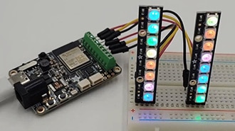
Solder Terminal blocks
Solder 2.54mm/0.1" Pitch Terminal Block - 4-pin to make connections modular.
These are compatible with the V2 3D printed case for the Mini Sparkle Motion with terminal cutout.
Ground on the matrix connects to G on the board.
Input wire on the matrix connects to 33 pin on the board.
5V on the matrix connects to 5V on the board.
Power with USB Host cable
Connect a USB-A Plug to USB-C Plug Adapter into the Mini Sparkle Motion port.
Connect the A connector to the USB host socket. The MicroB OTG plug connects to the port on the DJI Mavic Pro.
WLED Software
Board Choices
WLED runs on several different boards in Adafruit's collection. There are different benefits to each, but the installation process is largely the same. This page contains instructions for multiple boards -- be sure to use the pinouts and installation instructions for the one you're using.
Sparkle Motion
This is our flagship ESP32 board, designed with WLED and Xlights in mind. It has 4 outputs and is set up to drive either 5v, 12v or 24v pixels. It's a workhorse of a board and for larger projects it's the clear winner. It has an onboard microphone for instant sound-reactive support, and an IR sensor built in, to make it easy to control your project with an infrared remote. It also has a couple stemma ports so you can add your own sensors or peripherals.
Sparkle Motion Mini
The Sparkle Motion Mini is a smaller version of the Sparkle Motion board. It has two LED outputs, a microphone, and two stemma ports that make it easy to add an IR sensor or other peripherals. It's got an onboard NeoPixel and a small footprint, making it perfect for wearables or smaller projects. It will power a whole lot of pixels through the onboard USB port: it's safe to draw up to 4A through this port, giving you plenty of power for most wearable projects.
At this time, the Sparkle Motion Mini works best with WLED 0.15.1 -- the extra GPIO for the microphone pins are not supported in WLED 0.15.0. This should be fixed with the release of version 16.
To get mic support now, the following combined .bin file can be used. Get it by downloading this zip file:
esp32_bootloader_v4_WLED_0.16.alpha_ESP32.zip
To install, extract the .bin file from the zip and then follow the same ESB Web Flasher process used for installing CircuitPython. At the "Programming the Board" step, choose the .bin file and leave offset as 0x0.
QT Py Pico ESP32
The QT Py Pico is small and affordable, so usually my go-to for smaller costumes or wearables. It also has a range of BFF add-on boards that add functionality. Here's a guide with more QT Py info. The QT Py will drive up to around 30 pixels through the onboard USB port, so if you have more LEDs than that you may want to consider the Sparkle Motion Mini instead, or you can power the board through the +5v pin.
Note: WLED works on the QT Py Pico but NOT on the S2 or S3 versions, at the time of writing.
Feather Huzzah ESP32
The Feather Huzzah ESP32 the top of the line. It's a great choice for projects where you want to add sensors, interaction, or drive a whole lot of LEDs. It's the most reliable as well -- I've run these for two months straight with no power cycling and they just keep on truckin. Adafruit has a very wide selection of Feather Wing boards that connect to the Feather microcontroller line. The sky is the limit with these boards.
It also comes in a version with a high-powered WiFi range extender! If you're trying to sync multiple instances across distance, check this one out. Feather Huzzah ESP32 V2 w.FL Antenna
Feather Huzzah ESP8266
The Feather Huzzah ESP8266 will run WLED as well but won't drive as many pixels: the ESP32 limit on WLED is around 1000 pixels per input, but the ESP8266 tops out at around 500. It's about $5 cheaper though, so for smaller projects it's a great way to save a little money and still have access to all the Featherwing options in the Adafruit store.
Driver Update
Some versions of our controllers have a new serial chip which needs a driver installed before we can install WLED. Head over to our How to Install Drivers for WCH USB to Serial Chips tutorial and download and install the new driver.
If you have an older QT Py with CP2102 USB-to-Serial bridge, use SiLabs’ driver instead.
Install WLED
These next steps require a Web Serial-compatible browser. As of this writing, that means Google Chrome, Microsoft Edge or Opera “desktop” browsers. Other browsers (Safari, Firefox, Explorer and anything mobile) won’t work.
Visit https://install.wled.me/
Plug your microcontroller into your computer with a known good USB cable. Click "Install" and select the port for your board.
Depending on the USB-to-serial bridge chip on the board, you might see one or two serial ports. On Mac, for instance, there might be both “/dev/cu.usbmodem[number]” and “/dev/cu.wchusbserial[number]”. Use the “wchusbserial” one.
After successful installation, enter your WiFi network name and password when prompted. This must be a 2.4 GHz WiFi network; ESP32 does not support 5 GHz networks. If it can’t connect, then as a fallback WLED will create its own 2.4 GHz WiFi access point.
Sometimes the "Connect to Wi-Fi" prompt doesn't show up. Don't panic, just see the step below on connecting your computer or mobile device to the WLED-AP access point created on the microcontroller itself!
If you don't see the "Connect to Wi-Fi" prompt, you'll need to set up your WiFi network using AP (access point) mode. Open up your WiFi settings and look for a WiFi network called WLED-AP. (Note, this access point can take up to 30 seconds to appear sometimes.) Connect to this network using the default password wled1234. The WLED interface will pop up in its own captive browser window.
From here, go into Config/Wifi Settings and enter your WiFi credentials for the access point you normally use near the top.
Give your project a name in the mDNS field a little further down the page. Now you can type in "projectname.local" (where "projectname" is your mDNS name) into any web browser on the same wifi network to access your microcontroller.
You can also scan the QR code below to open access point mode.
For more help and troubleshooting tips visit the Getting Started page on the WLED knowledge base.
Setup & Preferences
WiFi Setup
Head to the WiFi Setup screen under Config and create a good URL so you can control your project from any web-enabled device. Call it something you'll remember, that's easy to type into any web browser on your WiFi network in order to connect to your project.
In Safari or Chrome on your phone or computer, type in this web address to access the WLED interface: http://projectname.local (where "projectname" is whatever you put into this field).
Check out the Additional Settings page for more info on accessing your project. WLED has an "access point mode" that doesn't require a WiFi network for when you're out on the go. It's also helpful to download one of the WLED apps to help manage and organize your projects.
LED Preferences
Next, head to the LED Preferences tab under the Config menu.
Scroll down to Hardware Setup. Put your total number of LEDs into the "Length" field, and change GPIO to the pin number associated with the pin you soldered to. Check the pinout diagram for the board you're using (it's the number in yellow).
Use It
Now you can use any computer or handheld device to control your LEDs.
Make sure your device is on the same WiFi network as your board. Navigate to your custom URL (projectname.local/ ) in a web browser. You'll see a color picker above a whole bunch of color palette choices.
Choose a color, choose an effect, and watch your lights animate and glow!
Save your favorite combinations as presets, create playlists, control the speed and intensity of the animations, and lots more. This web app is incredibly intuitive and easy to use.
Head over to the WLED wiki at https://kno.wled.ge/ to delve into all the particulars.
WLED Configuration
LED Settings
The 20x20 NeoPixel matrix will need to be configured in order to display the animations correctly. Follow the settings below to configure the LED matrix.
Click on the Config icon on the homepage of WLED, then click on LED Preferences
Under section LED outputs set the following
1: WS281x
mA/LED: 35aA (eco WS2812)
Color order: RGB
Start: 0 Length: 400
Data GPIO: 33
Click save at the top when settings have been updated.
2D Configuration
In the Configuration menu, click on 2D configuration and make the following settings.
Under the 2D setup section, select 2D matrix from the dropdown menu.
Under the LED panel layout section make the following adjustments
1st LED: Top Left
Orientation: Vertical
Serpentine: Off
Dimensions: 20 x 20
Click save at the top when settings have been applied.
2D Effects
On the WLED homepage, under the Effect mode, click on the search box. In the categories popup, click on the matrix icon. The list of effects will filter out all effects and will show all available 2D effects. Click on any of these effects to display on the 20x20 NeoPixel Matrix.
Exporting Presets
Follow the link for instructions to export presets:
https://kno.wled.ge/features/presets/
PIXEL MAGIC TOOL Process
This tool helps converts images into code in JSON WLED format for 2D Matrix panels! This is perfect for adding an animated gif to the display.
Most gifs will work, but images pixel detail with an animation with 5 frames or less will show up the best on the matrix.
Download the .htm file from https://github.com/ajotanc/PixelMagicTool and upload the .htm file to the Sparkle board. Use the UI to navigate the files on host.local address http://customname.local/edit
Now you can navigate to http://customname.local/pxmagic.htm to see the UI and upload images
Load Saved Preset Animations
You can load the presets created for this project below. Once loaded you can Create add each preset frame into a playlist to play in order.
Creating Custom Animations
Add the host name with the .local ending.
Add the preset name for your image.
Brightness: To save battery power set to about 80.
Enable Animation, Transparent image and Resize image.
Set the width and height to 20x20.
Drag and drop an image into the selection box and tap on generate to preview the layout.
Tap save to export each frame as a preset into WLED.
Arrange Presets into a Playlist
Pixel Magic will save each frame as a Preset. Tap the +Playlist button and add each Preset in order to the playlist.
Inside the new playlist you can set the length of each frame, transition timing, how many times to loop and even set each frame to shuffle the frames to add randomness to the an animation like the eye gif.
Build multiple playlists and have them play in a loop by selecting which playlist plays after it completes.
Assemble
Assemble the Mini Sparkle Motion case
Place the board aligned to the USB C cutout.
Align the terminal cutout on the lid and press fit the edges to snap together.
Mount case
Use M2.5x8mm screws to mount the case to the back leg. Place screws in the center of each tab and fasten to the screw hole on the back leg part.
Attach Back Leg
The tabs on the back leg snap into the existing back leg loops by inserting at an angle. Bending the second tab to press fit into the leg loop.
Drone USB port
The Mirco USB host cable connects to the port on the side of the drone.
Attach front legs
Align the triangular shapes on the legs and insert the drone leg into the printed leg extenders.
Attach arm clips
Align the trapezoidal clips to the front and back arms with the loops pointed down. Firmly bend the clips back to fit over the arms.
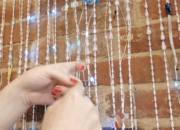
Prepare LED Net
Use a green metal garden stake to hold the LED net up.
Cut the stake to 36" inches wide and thread the stake over and under the net at the top (under the square boxes).
Connect the stake to the arm clips with nylon fishing line.
Measure two 34" inch pieces of line and tie both ends to each side of the stake to create a loop.
Connect line to arms
The nylon lines are inserted into the clips through the cutouts. Pass lines into the loops on the left, back and front arms. Repeat for the right, front and back arms.
Flying the Matrix
Position Net for take off
Lay the LED net to the back of the drone. Keep the net back far enough so the line is taut, pulled tight, with no slack or looseness to avoid the blades.
Make sure to take off slowly.
While in the air make sure to maintain direct sight. Wind gusts will rock the drone and make it drift. Fly in open areas.
To land, slowing lower altitude. Once the net touches the ground, slowing fly forward while descending to avoid catching the net.