Mfr Part # 6159
NEOPIXEL LED OUTDOOR NETTING - 2
Adafruit Industries LLC
License: See Original Project Addressable LEDs Hand Tools LED Matrix Solder / Desoldering Wifi Wireless
Courtesy of Adafruit
Guide by Erin St Blaine
Overview
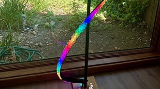
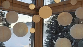
Add hundreds of lights to your home or yard with these fantastic Pebble Pixel Nets. Adafruit carries them in a variety of sizes, from 1x1m to 1x6m large, and they are chainable and expandable, so no vision is too big.
These nets use 12v power, which can be easily handled by the Adafruit Sparkle Motion microcontroller. It has 4 powered LED outputs, a power manager so you can run 12v or 5v lights, and an onboard I2S microphone, which makes sound-reactive projects a snap.
The build is fairly easy, with no soldering required (though adding connectors can make your life easier). This gives you time to focus on making beautiful sequences and enjoying your pretty lights.
WLED and xLights
Both WLED and xLights are open-source control software for LEDs. The Sparkle Motion board works great with both. What's the difference?
WLED is a fast and easy way to get your lights doing beautiful things. It's easy to install and configure, and you can be up and running within just a few minutes. WLED's software lives on the microcontroller and works over your local WiFi network to talk to each controller. It's easy to sync your projects together and use the preset animations and customize them to a certain extent. I use WLED when I want to "set it and forget it" -- the controller boots up when I power it on and then the animations just run automatically.
xLights is a more advanced option, and its biggest strength is sequencing. This program is used by industry professionals and also by homeowners who want a crazy mad holiday display in their front yard, with animated trees, windows, roof lines, arches, and matrices. xLights makes it possible to run animations across all your different lights at once. It's free to download and use, and there are online communities where people share and sell their favorite sequences. xLights really shines when it's showtime: sequence all your different lights to a piece of music and impress the heck out of your neighbors.
To run xLights you first need to install and configure WLED, so work through that section first.
Parts
NeoPixel LED Outdoor Netting - 20 x 20 LEDs - 1x1 Meter Sizing
NeoPixel LED Outdoor Netting - 80 x 20 LEDs - 1x4 Meter Sizing
These nets require 12v power. For just 1-2m of net, this 5a power supply is just fine. If you're using the bigger nets or chaining multiple nets together, or if you're doing an outdoor installation, look for a beefier power supply.
This net will also run on battery power. Our 8 x AA battery holder supplies 12v and will run a 1-2m net for several hours. It's insufficient for larger projects, but sometimes a few hours is all you need.
Connectors & Wire
Using connectors allow you to remove your Sparkle Motion controller from your project, which is especially helpful when it's a larger scale project that's hard to move. Adding 3-pin JST connectors is a bit more work during setup but can save you a lot of time down the road. They're pretty weatherproof and hold up to wind and rain. I like these color-coded ones.
Get some heat-shrink tubing too!
1 x Heat Shrink Tubing
For a Large Install
Bigger (800+ pixel) installations will require thicker wire connections and more power. Here are a couple suggestions to get you started.
Standard JST connectors won't work in this case: the wires inside those little connectors just aren't rated to carry that much current. Solder your wires together or use a 12v rated connector like these.
Wiring Diagram
These nets are 20 pixels wide with 5mm spacing. A 1m net is a 20x20 square and contains 400 pixels.
The Sparkle Motion board has 4 outputs: 3 in the screw terminal and another using the pins just to the left of it. WLED prefers no more than 800 pixels per output (though it will work with more, just not as smoothly) and xLights sets a hard limit of 1000 pixels per output.
Keep this in mind when you're setting up your project. For the larger nets with 1200-1800 pixels, you may want to add a second data line that connects into the net after the first 800 pixels, for best performance.
It's also a good idea to connect another power line at the far end of the net -- the manufacturers have broken out power injection wires every 800 pixels on the bigger nets to make this easy. If you're getting flickering or voltage, drop across the pixels, try adding another power injection point.
The Sparkle Motion is built to power LEDs, but for very large projects with larger power draws, it's a good idea to run the power directly to the lights instead of pulling it all through the board.
How many LEDs Can I Connect?
The Sparkle Motion board has four outputs for LED strips: 3 in the screw terminal and one more using the GPIO pins next to the screw terminal. It has a "Classic" ESP32 chip onboard.
Driving Pixels with WLED
From the WLED Knowledge base:
For perfect performance, it is recommended to use 512 LEDs/pin with 4 outputs for a total of 2048 LEDs.
For very good performance, it is recommended to use 800 LEDs/pin with 4 outputs for a total of 3200 LEDs.
For good performance, you can use 1000 LEDs/pin with 4 outputs for a total of 4000 LEDs.
For okay performance, you can use 1000 LEDs/pin with 5 outputs for a total of 5000 LEDs.
For okay performance, you can use 800 LEDs/pin with 6 outputs for a total of 4800 LEDs.
ESP32 can calculate about 65k-85k LEDs per second (that means 1000 LEDs @~70fps, 2000 LEDs @~35fps, 4000 LEDs @~18fps)
4 outputs seem to be the sweet spot.
How Do I Power It?
For Adafruit's 1x1 meter net, these power supplies will work great.
For larger projects (more than 800 pixels), or projects that will be placed outdoors, try this power supply (or similar):
For wearable or portable projects, you can use this 8xAA battery pack for 12v pixels. But if you're making a wearable project, you might also want to check out the Sparkle Motion Mini board. It's not quite as powerful and won't drive 12v pixels but can power up to 4A at 5v and that's plenty for most costume pieces. Check out our 5v Pebble Pixels to go along with it.
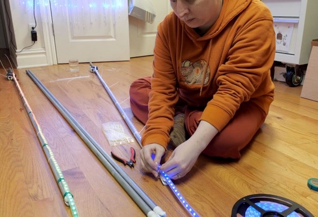
Assembly - Small Projects
Adafruit LED nets have a couple different wires coming off them. Look for the wire labeled "input". Each of the 3 wires has a label too! Handy.
I like to wire a 3 pin JST connector between the net and the Sparkle Motion board. This is not necessary: it's totally possible to wire the net directly to the Sparkle Motion board's screw terminal.
If you're not using JST connectors, then go ahead and insert the 3 input wires into the screw terminal on the Sparkle Motion Board: 12v to +, DI to 19, and G to G. Otherwise, solder the female side of your JST connector to the input wires on the net. I like to use red for +12v, green for data, and black for G.
The 2-strand wire on the net is for power injection. The larger nets have this attached in the middle to make your life easy. You can also inject power at the far end. A good rule of thumb is to inject power every 800 pixels or so.
Use a tiny precision flat head screwdriver to carefully and gently open the ports on the screw terminal. These are pretty easy to break so be gentle. Look carefully at the openings as you turn the screws. When you see a square opening appear, stop turning.
Strip about 1/8" of wire from the 3 net or connector wires and insert carefully into the screw terminals. Gently tighten the screw until it's snug: about 5 turns -- it shouldn't turn freely, if it does, you've got the wire in the wrong part of the hole so pull it out and try again.
The wires should not come out easily when you tug. But, as we know, these controllers get tugged on all the time! After testing to be sure of my connections, I added a zip tie around the back of the controller to create strain relief on the connectors.
LED strips often come with these connectors already attached, but there seems to be no standard for whether the factories attach the male or the female connector on the "in" end. For my own peace of mind, I try to be consistent and always use the male side of the connectors on the microcontrollers, and the female on the "in" end of my LED strip. Data is flowing "out" from the microcontroller and "in" to the strip, so the male/female metaphor makes good sense in this arrangement.
There is also no standard as to which way the color coding is wired on these connectors. Some have a red wire on the left side, some on the right side. Some have no color coding at all.
Hooking your strips up "backwards" (accidentally connecting a red wire to a black wire) can damage your board and your LEDs, so it's important to be really careful when you're setting up your connectors.
Be as consistent as possible with color coding and throw away any connectors you've got in the drawer that are wired "backwards" from the rest.
Connect the net to the controller and plug the controller in with at 12v power supply. These boards come pre-loaded with a rainbow animation on pin 19, so if your lights come on, you've got it right and you're good to go.
Troubleshooting
No lights? Here are a few things to try:
Check your wire connections. These screw terminals can be tricky to manage, and they break pretty easily. Try using a different set of holes if you think your connections might be the problem
Get WLED installed and running on your microcontroller
Be sure you're connecting to the "input" end of the net and not the "output" end. These nets are directional and will only work if you connect to "in"
If your lights are on but are super dim or flickering, you may have a powering issue. Try power injection or try using a screw terminal to power the lights directly instead of through the board
Assembly - Big Projects
For larger projects with more than 800 pixels or so, the wiring gets a little bit more complicated. It's not a good idea to pull too much power through the Sparkle Motion board, and bigger LED installations can draw a fair amount of power.
You'll also want to start a new data line every 800 pixels or so if you're planning to run WLED or xLights on your Sparkle Motion Board.
Find the input end of your net. It should be labeled by the manufacturer.
Solder a 3-pin JST connector to the 3 wires, and at the same time, splice in a beefy (16-18g) power and ground wire. I'm using 16-gauge lamp cord here, but there are lots of options available with different form factors.
This higher current power supply is a bit too much for most of the standard JST connectors. They use very skinny wire inside and can burn up pretty quickly.
For the very best power transfer, hard-wire the 16-gauge power wires to your power supply. If you want a removable power supply, try using these 2-pin wire joints to connect the wires. They can handle the 12v current.
Data Outputs
If you're running WLED or X-lights, these controllers work best at around 800-1000 pixels per output. Adafruit 4-meter nets have 1600 lights. So, for these nets, for best performance, it's a good idea to run a data line to the middle of the net and connect it up right after pixel 800.
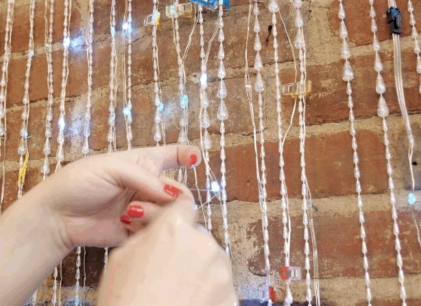
On the 4m net there's a power injection wire soldered on at this point, so it's easy enough to find. It's the unbroken wire along the bottom that we want. Carefully separate it from the other wires and cut it carefully in the middle. Solder a long wire to the "in" for the second half of the net.
I wove this wire and the power injection wire through the plastic connectors at the top of the net to keep them from getting pulled or hanging down.
Connect the data wire and the two power injection wires to a female JST connector and then to your Sparkle Motion board.
Splice the power wires coming from the power supply to the power injection lines as well. This will work best if power is flowing directly from the power supply to the lights for each power injection point.
It's possible to use the 3rd and 4th input on the board to control more nets and lights. With xLights or WLED you can also sync multiple controllers together, so expansion is pretty easy.
WLED Setup
This section will show how to install and set up WLED on your Sparkle Motion board and set up a 2-dimensional matrix so you can run mapped, 2D animations on your net.
The Sparkle Motion board has a lot more features we're not covering in this guide. It has an onboard I2S microphone, for instant audio-reactive projects. It has an IR sensor so anyone can control your project with a simple infrared remote. There are a lot of settings and features that can really make your project shine.
Check out the Sparkle Motion Guide for information on how to use these features and more.
Adafruit Sparkle Motion
By Erin St Blaine
WLED Software
Board Choices
WLED runs on several different boards in Adafruit's collection. There are different benefits to each, but the installation process is largely the same. This page contains instructions for multiple boards -- be sure to use the pinouts and installation instructions for the one you're using.
Sparkle Motion
This is our flagship ESP32 board, designed with WLED and Xlights in mind. It has 4 outputs and is set up to drive either 5v, 12v or 24v pixels. It's a workhorse of a board and for larger projects it's the clear winner. It has an onboard microphone for instant sound-reactive support, and an IR sensor built in, to make it easy to control your project with an infrared remote. It also has a couple stemma ports so you can add your own sensors or peripherals.
Sparkle Motion Mini
The Sparkle Motion Mini is a smaller version of the Sparkle Motion board. It has two LED outputs, a microphone, and two stemma ports that make it easy to add an IR sensor or other peripherals. It's got an onboard NeoPixel and a small footprint, making it perfect for wearables or smaller projects. It will power a whole lot of pixels through the onboard USB port: it's safe to draw up to 4A through this port, giving you plenty of power for most wearable projects.
At this time, the Sparkle Motion Mini works best with WLED 0.15.1 -- the extra GPIO for the microphone pins are not supported in WLED 0.15.0. This should be fixed with the release of version 16.
To get mic support now, the following combined .bin file can be used. Get it by downloading this zip file:
esp32_bootloader_v4_WLED_0.16.0-alpha_ESP32.zip
To install, extract the .bin file from the zip and then follow the same ESB Web Flasher process used for installing CircuitPython. At the "Programming the Board" step, choose the .bin file and leave offset as 0x0.
QT Py Pico ESP32
The QT Py Pico is small and affordable, so usually my go-to for smaller costumes or wearables. It also has a range of BFF add-on boards that add functionality. Here's a guide with more QT Py info. The QT Py will drive up to around 30 pixels through the onboard USB port, so if you have more LEDs than that you may want to consider the Sparkle Motion Mini instead, or you can power the board through the +5v pin.
Note: WLED works on the QT Py Pico but NOT on the S2 or S3 versions, at the time of writing.
Feather Huzzah ESP32
The Feather Huzzah ESP32 the top of the line. It's a great choice for projects where you want to add sensors, interaction, or drive a whole lot of LEDs. It's the most reliable as well -- I've run these for two months straight with no power cycling and they just keep on truckin. Adafruit has a very wide selection of Feather Wing boards that connect to the Feather microcontroller line. The sky is the limit with these boards.
It also comes in a version with a high-powered WiFi range extender! If you're trying to sync multiple instances across distance, check this one out. Feather Huzzah ESP32 V2 w.FL Antenna.
Feather Huzzah ESP8266
The Feather Huzzah ESP8266 will run WLED as well but won't drive as many pixels: the ESP32 limit on WLED is around 1000 pixels per input, but the ESP8266 tops out at around 500. It's about $5 cheaper though, so for smaller projects it's a great way to save a little money and still have access to all the Featherwing options in the Adafruit store.
Driver Update
Some versions of our controllers have a new serial chip which needs a driver installed before we can install WLED. Head over to our How to Install Drivers for WCH USB to Serial Chips tutorial and download and install the new driver.
If you have an older QT Py with CP2102 USB-to-Serial bridge, use SiLabs’ driver instead.
Install WLED
These next steps require a Web Serial-compatible browser. As of this writing, that means Google Chrome, Microsoft Edge or Opera “desktop” browsers. Other browsers (Safari, Firefox, Explorer and anything mobile) won’t work.
Visit https://install.wled.me/
Plug your microcontroller into your computer with a known good USB cable. Click "Install" and select the port for your board.
Depending on the USB-to-serial bridge chip on the board, you might see one or two serial ports. On Mac, for instance, there might be both “/dev/cu.usbmodem[number]” and “/dev/cu.wchusbserial[number]”. Use the “wchusbserial” one.
After successful installation, enter your WiFi network name and password when prompted. This must be a 2.4 GHz WiFi network; ESP32 does not support 5 GHz networks. If it can’t connect, then as a fallback WLED will create its own 2.4 GHz WiFi access point.
If you don't see the "Connect to Wi-Fi" prompt, you'll need to set up your WiFi network using AP (access point) mode. Open up your WiFi settings and look for a WiFi network called WLED-AP. Connect to this network using the default password wled1234. The WLED interface will pop up in its own browser.
From here, go into Config/Wifi Settings and enter your WiFi credentials near the top. Give your project a name in the mDNS field a little further down the page. Now you can type in "projectname.local" (where "projectname" is your mDNS name) into any web browser on the same wifi network to access your microcontroller.
You can also scan the QR code below to open access point mode.
For more help and troubleshooting tips visit the Getting Started page on the WLED knowledge base.
Setup & Preferences
WiFi Setup
Head to the WiFi Setup screen under Config and create a good URL so you can control your project from any web-enabled device. Call it something you'll remember, that's easy to type into any web browser on your WiFi network in order to connect to your project.
In Safari or Chrome on your phone or computer, type in this web address to access the WLED interface: http://projectname.local (where "projectname" is whatever you put into this field).
Check out the Additional Settings page for more info on accessing your project. WLED has an "access point mode" that doesn't require a WiFi network for when you're out on the go. It's also helpful to download one of the WLED apps to help manage and organize your projects.
LED Preferences
Next, head to the LED Preferences tab under the Config menu.
Scroll down to Hardware Setup. Put your total number of LEDs into the "Length" field and change GPIO to the pin number associated with the pin you soldered to. Check the pinout diagram for the board you're using (it's the number in yellow).
Use It
Now you can use any computer or handheld device to control your LEDs.
Make sure your device is on the same WiFi network as your board. Navigate to your custom URL (projectname.local/ ) in a web browser. You'll see a color picker above a whole bunch of color palette choices.
Choose a color, choose an effect, and watch your lights animate and glow!
Save your favorite combinations as presets, create playlists, control the speed and intensity of the animations, and lots more. This web app is incredibly intuitive and easy to use.
Head over to the WLED wiki at https://kno.wled.ge/ to delve into all the particulars.
WLED Config
Next, we'll tell WLED about our physical setup. We'll give our project a name and easy-to-remember URL and tell the software how many LEDs we have set up on each pin.
WiFi Setup
Head to the WiFi Setup screen under Config. This is where your network credentials live, so you can change them if needed. Scroll down to the mDNS field and create a good URL so you can control your project from any web-enabled device. Call it something you'll remember, that's easy to type into any web browser on your WiFi network in order to connect to your project.
In this example, I'd go to my web browser on my phone, iPad, or computer, and type in "http://projectname.local" to open up the WLED interface on my screen. Your device must be on the same WiFi network as your board.
LED Preferences
Next, head to the LED Preferences tab under the Config menu.
Scroll down to Hardware Setup. The Sparkle Motion board has 4 spots to attach LED strips: the screw terminal uses GPIO 19, 22, and 21 and the through-hole solder pads to the left of the screw terminal is GPIO 23.
WLED allows up to 4 strips to be connected at once. The strips can be of different types, lengths, and color order. Select your LED type, length, and GPIO pin. If you have multiple strips connected, click the + button and enter the additional strips in the same way.
Click "save" and if you've done everything correctly, your light strands should come on in a warm, cheerful yellow color. Success! Time to start making pretty light animations.
Troubleshooting
If your lights didn't come on, here are a few things to try:
Head back to WLED and check your pinout configuration under LED Preferences. Be sure the pin number is the correct GPIO for the attachment point you used.
Check your wiring! Be sure you connected to the IN end of the LED strip. These strips can be inconsistent, so this is a pretty common problem. Use an alligator clip to try connecting the data wire on the other end (the power and ground wires should work from either end).
Try re-uploading the WLED software.
If the lights come on but you can't control them: i.e., you type in "projectname.local" into your browser and it won't connect, make sure you're on the correct WiFi network. If you're on a different network than the one you set up the sofware on, you won't see the WLED connection.
If your lights came on in blue or green instead of yellow, your color order is wrong. See below to fix.
If only half your lights came on, be sure you've got the correct number in the "length" field under LED preferences.
If your lights came on in a variety of weird colors and looking like a 1950s diner interior, you may have the wrong LED strip type selected. RGBW strips and RGB strips are not the same, so be sure you've got the correct strip type, or you'll get very odd behavior.
If your microcontroller hangs or keeps rebooting, or gets really hot, you may have the power and ground lines switched. Unplug right away and check: this is a fast way to brick your controller.
Color Order
If your lights have come on in any color other than a warm yellow, there's one more setting to change. LED strips and pixels are not all standardized, and sometimes the red, green, and blue LEDs inside are connected in a different order.
In the main interface window, choose "solid" as your effect and red as your color from the color picker.
If your lights come on in any color other than red, your color order is set incorrectly. This is an easy fix. Head back to the LED settings tab and find the Hardware Setup section (this is where you set up your pin number earlier). Choose BRG from the dropdown, click save, and see if your pixel colors match your color picker now. If not, try another combo until the lights look correct.
WLED 2d Matrix
If you're planning to set up xLights on this board once you're done installing WLED: STOP. The 2-d setup can make xLights setup go haywire. Set up your xLights matrix models first, then come back and set up the 2-d matrix in WLED.
If you're using a 2-d matrix such as an LED curtain or net, WLED has a handy 2d-matrix setup feature that will take care of the mapping for you. Head to Config and choose the 2D Configuration tab.
Check out these tutorials for more about 2d mapping with WLED:
Change the dropdown to read 2d Matrix, and additional options will appear. If you want to sync more than one panel, you can do it here.
Set up your layout numbers to match the number of rows and columns in your project. These nets have 20 pixels in a row and 20 pixels per meter.
You can also change orientation here - my pixels start in the lower left corner and finish in the upper right.
Matrix Effects
WLED has a hefty number of matrix effects that appear in the list when you've got your 2d matrix set up. Many of them can be customized with speed and intensity sliders, or different color palettes. Go wild!
xLights Setup
To get xLights installed, head over to the xLights Quick Start Guide. This will walk you through downloading and installing the software. Be sure to install the Vamp Plugins as well.
Once the software is installed, head to the Controllers tab to set up your Sparkle Motion board.
Controller Setup
Be sure your Sparkle Motion board is set up with WLED and plugged in to power. It doesn't need to be plugged into your computer, just running on the same WiFi network.
Click "Add Ethernet" and set up your board as shown. Mine is called Butterfly1 in WLED so I kept the same name in xLights. Choose WLED as the vendor and model, and Generic ESP32 as the variant. Change the protocol to DDP. Click save.
Model Setup
Next head to the Layout tab. Click the Matrix tool and draw a box in the black area - don't worry about the size or shape yet just get it onto the field.
Click one of the dots on the matrix to select it. In the lower left, set up the parameters as shown. Give it a name and click the "Don't Zig Zag" box since our matrix is not serpentine.
Under # Strings, enter 1. This means there's one data line feeding all the LEDs
Nodes/String: total number of pixels on this data line. Enter 400 for a 1-meter net or 800 for a 2-meter net
Strands/String: Total number of rows in your net. 20 for a 1m net or 40 for a 2m net
Starting Location: Change this so it matches your net's orientation
If you have a 4-meter net, or two smaller nets you'd like to "merge" into one, add a second matrix and set it up the same way. For my setup. I'm using one 4m net and I have attached a second data line at the 801st pixel. Drag it into place under the first matrix to line it up.
If you have multiple models, you can create a Group. I've grouped my two net sections into one group called Net1. When I run animations on the Group, the whole net will act as one continuous matrix instead of two separate pieces.
Save your models once you're happy with the layout.
Connect Ports
Head back to the Controllers tab and select "Visualize". Drag your model(s) to the ports you've connected to on the Sparkle Motion board. The screw terminal ports are 1, 2, and 3 and the pin pad is 4.
Close the port window and click "Save". Then click the "Upload Output" button to send the configuration to the controller.
Create a Sequence
Let's create a test sequence and see if we can get our lights responding. In the "Sequence" tab in xLights, go to File > New Sequence.
For now, just to keep things simple, choose Animation and 20 FPS (frames per second). This will create a sequence that's populated with your models and ready to test your lights.
Select the "Butterfly Effect" animation and drag it to your timeline, on the line that has your matrix model or group. Drag the handle out so the effect takes up a good chunk of the timeline, and press "play". You should see the animation appear on the onscreen model in the lower left of the screen.
To send your sequence to the LED net, click the light bulb button in the top center of the screen.
Troubleshooting
If your net doesn't respond, here are a few things to try:
Check your settings in WLED. Be sure the board is working and showing animations on the net before setting up your controller in xLights
If you've set up a 2D matrix in WLED, try setting it back to 1D strip before configuring xLights. Having two different matrix definitions can confuse things
Be sure you've saved your controller settings and clicked "Upload Output"
If your matrix is trying to join 20 ports on the controller, change the "string" number to 1
Be sure your computer and the controller are on the same WiFi network
Did you click the light bulb icon? That's what turns the show on and off / starts and stops sending data to the lights
If it's just not working, try deleting all your models and controllers and start again
More Resources
xLights is a pro-level program with lots of functions and settings. It can be a little overwhelming at first, but the possibilities are grand. Here are a few links with tutorials and inspiration to get you started.
There are dozens of tutorials available on YouTube and even online courses available for learning this massively deep program. Go wild.