Mfr Part # 6100
SPARKLE MOTION PCB ANTENNA
Adafruit Industries LLC
License: See Original Project Addressable LEDs LED Strips Microcontrollers Wifi
Courtesy of Adafruit
Guide by Erin St Blaine and 2 other contributors
Overview
On macOS, you need to use this board with a hub and USB A to USB C cable to upload any software. If you plug the board directly into a USB C port on your Mac, it will assume it needs power delivery (PD) and the USB to Serial port will not work.
We mainly recommend this board for use with WLED and Xlights, but examples are included in this guide for CircuitPython and Arduino.
The Adafruit Sparkle Motion is the flagship in our series of "Sparkle Motion" boards, which are our attempt to make the best small WLED-friendly smart LED driving board in the whole world. Our resident mermaid, firepixie makes a lot of projects with WLED and she loves it! So how can we make something that will be powerful enough to drive advanced LED projects with built-in sensors.
This version has a built-in antenna so it's ready to go out-of-the-box.
This board has everything you could possibly want for big, small, or even massive WLED/xLights projects:
Power option 1 via USB Type C PD with a slide switch that selects between 5, 12 and 20V (24V pixels can usually run fine at 20V)
Power option 2 via 2.1mm DC jack, center positive
Low forward-voltage diodes so it’s good for up to 5A from either
5 Amp fuse to protect from over-current drive
ESP32 mini module with built in antenna port - the classic ESP32 has the best WLED support even if we'd prefer the 'S2 or 'S3. Comes with 4 MB of flash, dual core 240MHz Tensilica, WiFi, Bluetooth LE, and Bluetooth Classic support
USB-serial converter with auto-reset
Three output signal terminal block sets with power and ground for each - they'll be level shifted to 5V. Use 26-20AWG stranded or solid core wires, 5A rated
6 GPIO breakout pads with a fourth level-shifted output, and 3 more GPIO plus power and ground
Built-in I2S microphone for audio-reactive projects with digital quality audio
Built-in IR receiver for easy remote-control integration
Stemma QT I2C port to connect external sensors/OLED/etc
Separate analog/digital input JST port for analog input, potentiometer, microphone, or external IR receiver
User button on GPIO 0 plus Reset button
Red built-in LED on pin 4
Small built-in NeoPixel on pin 2
Compact enough you can use it for wearable projects - 1.3"x1.75" / 33mm x 45mm size with mounting holes
To make it super-fast to get started, terminal blocks are pre-installed: use any 20-26 AWG stranded or solid core wires with a flat-head screwdriver to attach semi-permanently.
While we recommend it for use with WLED, it will also work just fine as a compact ESP32 board for use with Arduino, ESP-IDF, MicroPython, CircuitPython or any other ESP32 supported codebase.
The Sparkle Motion board has it all. Designed with ease of use for larger scale LED projects using WLED and Xlights, we've packed it with features and components that will enable users to create incredible things.
Power via USB Type C PD with a slide switch that selects between 5, 12 and 20V (24V pixels can usually run fine at 20V)
OR via 2.1mm DC jack
Low forward-voltage diodes so it's good for up to 5A from either USB or the DC jack
5 Amp fuse to protect from overcurrent drive
ESP32 mini module with built in or optionally wFL antenna port (the classic '32 has broad support even if we'd prefer the 'S2 or 'S3)
Three output signal terminal block sets with power and ground for each: level shifted to 5V
6 GPIO breakout pads with a fourth level-shifted output, and 3 more GPIO plus power and ground
Built-in I2S microphone
Built-in IR receiver
Stemma QT I2C port to connect external sensors/OLED/etc
Separate analog/digital input JST port for analog input, potentiometer, microphone or external IR receiver
Compact enough you can use it for wearable projects - 1.3"x1.75" / 33mm x 45mm size with mounting holes
Add-ons: yes! OLEDs! Inertial Measurement Units! Sensors a plenty. All plug-and-play thanks to the innovative chainable design: SparkFun Qwiic-compatible STEMMA QT connectors for the I2C bus, so you don't even need to solder! Just plug in a compatible cable and attach it to your MCU of choice, and you’re ready to load up some software and measure some light. Seeed Grove I2C boards will also work with this adapter cable.
In addition to the Stemma QT connector, we also added an RGB NeoPixel (with controllable power pin to allow for ultra-low-power usage), a reset button (great for restarting your program or entering the bootloader), and a button on GPIO 0 for entering the ROM bootloader or for user input.
Onboard sensors include an IR receiver for easy remote control, and an I2S microphone, so you can quickly and easily add sound reactivity to your project.
To make it super-fast to get started, terminal blocks are pre-installed: use any 20-26 AWG stranded or solid core wires with a flat-head screwdriver to attach semi-permanently.
This board has everything you could possibly want for big, small, or even massive WLED/xLights projects.
Pinouts
On macOS, you need to use this board with a hub and USB A to USB C cable to upload any software. If you plug the board directly into a USB C port on your Mac, it will assume it needs power delivery (PD) and the USB to Serial port will not work.
The Sparkle Motion is a board with a lot of sparkly features. This page covers it all!
Pretty Pins on Github (PDF).
Power Pins
USB-C port - This is used for both powering and programming the board. You can power it with any USB C cable that is USB-PD rated for the current you'll draw. It is a 5V 5A input - you can use off-the-shelf USB battery packs for portable operation. It is connected to a 5 Amp resetting fuse to protect from overcurrent drive.
USB-PD slide switch - selects between 5V, 12V, and 20V. Connected to the built-in HUSB238 power delivery chip, which is on the I2C bus with address 0x8 (0x08).
Barrel Jack - 2.1mm DC jack, center positive. Accepts power up to 24V. It is connected to a 5 Amp resetting fuse to protect from overcurrent drive.
Power LED - The green LED, located between the USB C port and Barrel jack, indicates when the board is powered up.
+ Terminal Blocks - The 3 VOUT terminal blocks along right side provide 5V-24V power for your pixels. Use 26-20AWG stranded or solid core wires, 5A rated.
- Terminal Blocks - The 3 GND terminal blocks along the right side are common ground for all power and logic. Use 26-20AWG stranded or solid core wires, 5A rated.
3.3V - This pin, located on the top row of the 6 pins broken out in the bottom right corner of the board, is the output from the 3.3V regulator. It can supply 500mA peak.
G - This pin, located on the bottom row of the 6 pins broken out in the bottom right corner, is connected to the common ground.
ESP32 Module
The processor on the Sparkle Motion is an ESP32 mini module. The classic ESP32 has the best WLED support. Comes with 4 MB of flash, dual core 240MHz Tensilica, WiFi, Bluetooth LE, and Bluetooth Classic support.
NeoPixel Output Signals
On the right side of the board there are 3 terminal blocks for NeoPixel output signals. All signals are level shifted to 5V. Use 26-20AWG stranded or solid core wires, 5A rated.
21 - GPIO21, available as SIG1 in CircuitPython and 21 in Arduino.
22 - GPIO22, available as SIG2 in CircuitPython and 22 in Arduino.
19 - GPIO19, available as SIG3 in CircuitPython and 19 in Arduino.
Logic Pins
The Sparkle Motion has 4 general purpose "IO" pins broken out near the bottom right corner of the board and 1 additional GPIO available via the 3-pin JST port at the bottom edge of the board.
10 - GPIO10. This is the UART RX (receive) pin. Connect to the TX pin found on a breakout or device. This is separate than the 'debug UART' which is connected to the USB-to-Serial converter, so it will not interfere during upload. In Arduino use Serial1. In CircuitPython use board.RX.
9 - GPIO9. This is the UART TX (transmit) pin. Connect to the RX pin found on a breakout or device. This is separate than the 'debug UART' which is connected to the USB-to-Serial converter, so it will not interfere during upload. In Arduino, use Serial1. In CircuitPython, use board.TX.
23 - GPIO23. Available as D23 in CircuitPython and 23 in Arduino. This is a 5V level shifted output only! You can use it as another LED strip pin.
18 - GPIO18. Available as D18 in CircuitPython and 18 in Arduino.
27 / JST Port - GPIO27. It uses ADC2. One of the capacitive touch pins. Available as D27 or A0 in CircuitPython and Arduino.
Note you cannot read analog inputs on ADC2 once WiFi has started, as it is shared with the WiFi hardware.
STEMMA QT
This JST SH 4-pin STEMMA QT connector breaks out I2C (SCL, SDA, 3.3V, GND). It allows you to connect to various breakouts and sensors with STEMMA QT connectors or to other things using assorted associated accessories. It works great with any STEMMA QT or Qwiic sensor/device. You can also use it with Grove I2C devices thanks to this handy cable.
SCL - GPIO13
SDA - GPIO14
You can access this I2C port with board.STEMMA_I2C() in CircuitPython and Wire in Arduino.
NeoPixel and Red LED
There are two LEDs you can control in code.
NeoPixel LED - This addressable RGB NeoPixel LED, labeled Neo on the board, can be controlled with code. It acts as a status LED in CircuitPython and is connected to GPIO2. It is available in CircuitPython as board.NEOPIXEL, and in Arduino as PIN_NEOPIXEL.
Red LED - This little red LED, labeled LED on the board, is on or blinks during certain operations (such as pulsing when in the bootloader), and is controllable in code. It is available in CircuitPython as board.LED, and in Arduino as LED_BUILTIN or 4.
Buttons
There are two buttons on the Sparkle Motion
Reset button - This button restarts the board and helps enter the bootloader. You can click it once to reset the board without unplugging the USB cable or battery.
Boot button - This button can be read as an input in code. It is connected to pin GPIO0. It is available as board.BUTTON in CircuitPython, and BUTTON in Arduino. Simply set it to be an input with a pullup. This button can also be used to put the board into ROM bootloader mode. To enter ROM bootloader mode, hold down boot button while clicking reset button mentioned above. When in the ROM bootloader, you can upload code and query the chip using esptool.
IR Receiver
The IR Receiver on the top center of the board makes it easy integrate a remote control into your project.
IR - GPIO32. Available as board.IR in CircuitPython, and 32 in Arduino. It is connected to ADC1.
I2S Microphone
In the bottom center of the board is an I2S microphone, great for adding audio reactivity to your WLED projects. It uses three data pins:
DATA - GPIO25
WS - GPIO33
BCLK - GPIO26
You can use the microphone with WLED and Arduino. There is no I2S input support in CircuitPython at this time.
CH343DS1 USB-to-Serial Converter
The CH343DS1 USB to serial converter communicates between the ESP32 and your computer over USB. It is a full-speed USB device interface and is USB 2.0 compatible. It has an auto-reset circuit that works perfectly with any ESP32 uploading tool. Sometimes these chips require drivers to be installed on your computer's operating system. We have a Learn Guide detailing how to install these drivers.
UART Debug
On the back of the board, the hardware UART debug port has two broken out pads, labeled TX and RX on the board silk. You can connect these to a USB console cable in order to read the debug output from the ESP32 IDF while connected to a USB PD power supply. This is useful if you are writing software and need to see the low-level debug output.
TX - The pad on the top (closest to the Adafruit logo) is the TX pin.
RX - The pad on the bottom (furthest from the Adafruit logo) is the RX pin.
Connecting LEDs
On macOS, you need to use this board with a hub and USB A to USB C cable to upload any software. If you plug the board directly into a USB C port on your Mac, it will assume it needs power delivery (PD) and the USB to Serial port will not work.
Wiring Diagram
There are many different types of pixels available. This is a general reference that shows connection points for most types of strips. Your project may have different requirements, but this is a good starting point.
For NeoPixel strips or other strips that have 3 solder pads or wires, connect to the screw terminal at the base of the board. There are markings on the PCB showing which terminal is which. It's set up with three 3-pin strip connections in mind, and each strip has its own power and ground connection. The GPIO pins are labeled: 19, 22, and 21, and they're in the middle of each block of 3 wires.
If you'd like to add a fourth instance/strip, connect the data and ground to the pins next to the screw terminal as shown, and the power wire to one of the +5v screw terminal ports.
The two Stemma connector ports can be used to connect sensors or other peripherals.
How many LEDs Can I Connect?
The Sparkle Motion board has four outputs for LED strips: 3 in the screw terminal and one more using the GPIO pins next to the screw terminal. It has a "Classic" ESP32 chip onboard.
Estimating Power Requirements
Each individual NeoPixel draws up to 60 milliamps at maximum brightness white (red + green + blue). In actual use though, it’s rare for all pixels to be turned on that way. When mixing colors and displaying animations, the current draw will be much less. It’s impossible to estimate a single number for all circumstances, but we’ve been using 1/3 this (20 mA per pixel) as a gross rule of thumb with no ill effects. But if you know for a fact that you need every pixel on at maximum brightness, use the full 60 mA figure.
To estimate power supply needs, multiply the number of pixels by 20, then divide the result by 1,000 for the “rule of thumb” power supply rating in Amps. Or use 60 (instead of 20) if you want to guarantee an absolute margin of safety for all situations. For example:
60 NeoPixels × 20 mA ÷ 1,000 = 1.2 Amps minimum
60 NeoPixels × 60 mA ÷ 1,000 = 3.6 Amps minimum
The choice of “overhead” in your power supply is up to you. Maximum safety and reliability are achieved with a more generously sized power supply, and this is what we recommend. Most power supplies can briefly push a little extra current for short periods. Many contain a thermal fuse and will simply shut down if overworked. So, they may technically work, but this is the electronics equivalent of abusing a rental car.
Here is a guide giving more info on what that means in terms of power draw: Powering NeoPixels Guide. The power draw varies greatly depending on the type of pixels and the brightness, as well as the color choice.
Keep in mind, 60 mA is a worst-case estimate! We’ve written a whole separate tutorial on getting things under control: Sipping Power with NeoPixels.
Driving Pixels with WLED
For perfect performance, it is recommended to use 512 LEDs/pin with 4 outputs for a total of 2048 LEDs.
For very good performance, it is recommended to use 800 LEDs/pin with 4 outputs for a total of 3200 LEDs.
For good performance, you can use 1000 LEDs/pin with 4 outputs for a total of 4000 LEDs.
For okay performance, you can use 1000 LEDs/pin with 5 outputs for a total of 5000 LEDs.
For okay performance, you can use 800 LEDs/pin with 6 outputs for a total of 4800 LEDs.
ESP32 can calculate about 65k-85k LEDs per second (that means 1000 LEDs @~70fps, 2000 LEDs @~35fps, 4000 LEDs @~18fps)
4 outputs seem to be the sweet spot.
What Kind of LEDs Can I Use?
The Sparkle Motion board and WLED accept a wide variety of pixel types. Anything in the Adafruit store labeled as "NeoPixel" or "Dotstar" will work. You can use rings, strips, jewels, pebble pixels, stars, RGBW strips, or just about any RGB addressable pixels you can find in our shop.
This setup will NOT work with "dumb" RGB strips or analog strips. It's meant for strips with individually addressable pixels (strips where each pixel can become a different color) rather than the strips that can only show one color at a time.
How Do I Power It?
The Sparkle Motion board has onboard power management so you can use 5v, 12v, or 24v strips. The board will deliver up to 20v (which is usually sufficient for 24v pixels). Be sure your power supply matches the voltage the LEDs expect. Here are a few good options. Check the shop for more variations including power supplies with inline on/off switches.
For wearable or portable projects, you can use a USB battery with 5v pixels, plugged into the onboard USB-C port, or this 8xAA battery pack for 12v pixels. But if you're making a wearable project, you might also want to check out the Sparkle Motion Mini board. It's not quite as powerful and won't drive 12v pixels but can power up to 4A at 5v and that's plenty for most costume pieces.
A Word About Connectors
It's possible to direct-wire your LED strips or pixels into the screw terminal, but I find it easier and more convenient to use 3-pin JST connectors that can be permanently affixed to the Sparkle Motion board with strain relief, so they don't pull out. Then I can simply plug in whatever LED strip or strand I want to use.
LED strips often come with these connectors already attached, but there seems to be no standard for whether the factories attach the male or the female connector on the "in" end. For my own peace of mind, I try to be consistent and always use the male side of the connectors on the microcontrollers, and the female on the "in" end of my LED strip. Data is flowing "out" from the microcontroller and "in" to the strip, so the male/female metaphor makes good sense in this arrangement.
There is also no standard as to which way the color coding is wired on these connectors. Some have a red wire on the left side, some on the right side. Some have no color coding at all. Hooking your strips up "backwards" (accidentally connecting a red wire to a black wire) can damage your board and your LEDs, so it's important to be really careful when you're setting up your connectors. Be as consistent as possible with color coding and throw away any connectors you've got in the drawer that are wired "backwards" from the rest.
Screw Terminal Connections
Use a tiny precision flat head screwdriver to carefully and gently open the ports on the screw terminal. These are pretty easy to break so be gentle. Look carefully at the openings as you turn the screws. When you see a square opening appear, stop turning.
Strip about 1/8" of wire from the 3 connector wires and insert carefully into the screw terminals. Use red for +, the middle wire for data, and the remaining wire for -. Gently tighten the screw until it's snug: about 5 turns -- it shouldn't turn freely, if it does, you've got the wire in the wrong part of the hole so pull it out and try again.
The wires should not come out easily when you tug. But, as we know, these controllers get tugged on all the time! After testing to be sure of my connections, I added a zip tie around the back of the controller to create strain relief on the connectors.
Connect the female side of the JST connector to your LED strip or strand, making sure the wire order matches the male connector in your screw terminal: +5v (red) should match up to +, data IN to GPIO, and G to G. Plug in your strand and power up the board. The board comes pre-loaded with a rainbow animation so your lights should come on if you've got everything hooked up right.
WLED Setup
On macOS, you need to use this board with a hub and USB A to USB C cable to upload any software. If you plug the board directly into a USB C port on your Mac, it will assume it needs power delivery (PD) and the USB to Serial port will not work.
The following pages will walk you through installing WLED and setting up the various features within the software. We will cover getting your lights turned on and responding to sound or IR control. We'll also show you how to connect sensors via the onboard Stemma port and add button control. And we'll show you how to set up multiple strands and multiple controllers and sync them together for larger scale projects.
Ready? Set? Let's go.
WLED Software
Board Choices
WLED runs on several different boards in Adafruit's collection. There are different benefits to each, but the installation process is largely the same. This page contains instructions for multiple boards -- be sure to use the pinouts and installation instructions for the one you're using,
Sparkle Motion
This is our flagship ESP32 board, designed with WLED and Xlights in mind. It has 4 outputs and is set up to drive either 5v, 12v or 24v pixels. It's a workhorse of a board and for larger projects it's the clear winner. It has an onboard microphone for instant sound-reactive support, and an IR sensor built in, to make it easy to control your project with an infrared remote. It also has a couple stemma ports so you can add your own sensors or peripherals.
Sparkle Motion Mini
The Sparkle Motion Mini is a smaller version of the Sparkle Motion board. It has two LED outputs, a microphone, and two stemma ports that make it easy to add an IR sensor or other peripherals. It's got an onboard NeoPixel and a small footprint, making it perfect for wearables or smaller projects. It will power a whole lot of pixels through the onboard USB port: it's safe to draw up to 4A through this port, giving you plenty of power for most wearable projects.
At this time, the Sparkle Motion Mini works best with WLED 0.15.1 -- the extra GPIO for the microphone pins are not supported in WLED 0.15.0. This should be fixed with the release of version 16.
To get mic support now, the following combined .bin file can be used. Get it by downloading this zip file:
esp32_bootloader_v4_WLED_0.16.0-alpha_ESP32.zip
To install, extract the .bin file from the zip and then follow the same ESB Web Flasher process used for installing CircuitPython. At the "Programming the Board" step, choose the .bin file and leave offset as 0x0.
QT Py Pico ESP32
The QT Py Pico is small and affordable, so usually my go-to for smaller costumes or wearables. It also has a range of BFF add-on boards that add functionality. Here's a guide with more QT Py info. The QT Py will drive up to around 30 pixels through the onboard USB port, so if you have more LEDs than that you may want to consider the Sparkle Motion Mini instead, or you can power the board through the +5v pin.
Note: WLED works on the QT Py Pico but NOT on the S2 or S3 versions, at the time of writing.
Feather Huzzah ESP32
The Feather Huzzah ESP32 the top of the line. It's a great choice for projects where you want to add sensors, interaction, or drive a whole lot of LEDs. It's the most reliable as well -- I've run these for two months straight with no power cycling and they just keep on truckin. Adafruit has a very wide selection of Feather Wing boards that connect to the Feather microcontroller line. The sky is the limit with these boards.
It also comes in a version with a high-powered WiFi range extender! If you're trying to sync multiple instances across distance, check this one out Feather Huzzah ESP32 V2 w.FL Antenna.
Feather Huzzah ESP8266
The Feather Huzzah ESP8266 will run WLED as well but won't drive as many pixels: the ESP32 limit on WLED is around 1000 pixels per input, but the ESP8266 tops out at around 500. It's about $5 cheaper though, so for smaller projects it's a great way to save a little money and still have access to all the Featherwing options in the Adafruit store.
Driver Update
Some versions of our controllers have a new serial chip which needs a driver installed before we can install WLED. Head over to our How to Install Drivers for WCH USB to Serial Chips tutorial and download and install the new driver.
If you have an older QT Py with CP2102 USB-to-Serial bridge, use SiLabs’ driver instead.
Install WLED
These next steps require a Web Serial-compatible browser. As of this writing, that means Google Chrome, Microsoft Edge or Opera “desktop” browsers. Other browsers (Safari, Firefox, Explorer and anything mobile) won’t work.
Visit https://install.wled.me/
Plug your microcontroller into your computer with a known good USB cable. Click "Install" and select the port for your board.
Depending on the USB-to-serial bridge chip on the board, you might see one or two serial ports. On Mac, for instance, there might be both “/dev/cu.usbmodem[number]” and “/dev/cu.wchusbserial[number]”. Use the “wchusbserial” one.
After successful installation, enter your WiFi network name and password when prompted. This must be a 2.4 GHz WiFi network; ESP32 does not support 5 GHz networks. If it can’t connect, then as a fallback WLED will create its own 2.4 GHz WiFi access point.
Sometimes the "Connect to Wi-Fi" prompt doesn't show up. Don't panic, just see the step below on connecting your computer or mobile device to the WLED-AP access point created on the microcontroller itself!
If you don't see the "Connect to Wi-Fi" prompt, you'll need to set up your WiFi network using AP (access point) mode. Open up your WiFi settings and look for a WiFi network called WLED-AP. (Note, this access point can take up to 30 seconds to appear sometimes.) Connect to this network using the default password wled1234. The WLED interface will pop up in its own captive browser window.
From here, go into Config/Wifi Settings and enter your WiFi credentials for the access point you normally use near the top.
Give your project a name in the mDNS field a little further down the page. Now you can type in "projectname.local" (where "projectname" is your mDNS name) into any web browser on the same wifi network to access your microcontroller.
You can also scan the QR code below to open access point mode.
For more help and troubleshooting tips visit the Getting Started page on the WLED knowledge base.
Setup & Preferences
WiFi Setup
Head to the WiFi Setup screen under Config and create a good URL so you can control your project from any web-enabled device. Call it something you'll remember, that's easy to type into any web browser on your WiFi network in order to connect to your project.
In Safari or Chrome on your phone or computer, type in this web address to access the WLED interface: http://projectname.local (where "projectname" is whatever you put into this field).
Check out the Additional Settings page for more info on accessing your project. WLED has an "access point mode" that doesn't require a WiFi network for when you're out on the go. It's also helpful to download one of the WLED apps to help manage and organize your projects.
LED Preferences
Next, head to the LED Preferences tab under the Config menu.
Scroll down to Hardware Setup. Put your total number of LEDs into the "Length" field and change GPIO to the pin number associated with the pin you soldered to. Check the pinout diagram for the board you're using (it's the number in yellow).
Use It
Now you can use any computer or handheld device to control your LEDs.
Make sure your device is on the same WiFi network as your board. Navigate to your custom URL (projectname.local/ ) in a web browser. You'll see a color picker above a whole bunch of color palette choices.
Choose a color, choose an effect, and watch your lights animate and glow!
Save your favorite combinations as presets, create playlists, control the speed and intensity of the animations, and lots more. This web app is incredibly intuitive and easy to use.
Head over to the WLED wiki at https://kno.wled.ge/ to delve into all the particulars.
WLED Config
Next, we'll tell WLED about our physical setup. We'll give our project a name and easy-to-remember URL and tell the software how many LEDs we have set up on each pin.
WiFi Setup
Head to the WiFi Setup screen under Config. This is where your network credentials live, so you can change them if needed. Scroll down to the mDNS field and create a good URL so you can control your project from any web-enabled device. Call it something you'll remember, that's easy to type into any web browser on your WiFi network in order to connect to your project.
In this example, I'd go to my web browser on my phone, iPad, or computer, and type in "http://projectname.local" to open up the WLED interface on my screen. Your device must be on the same WiFi network as your board.
LED Preferences
Next, head to the LED Preferences tab under the Config menu.
Scroll down to Hardware Setup. The Sparkle Motion board has 4 spots to attach LED strips: the screw terminal uses GPIO 19, 22, and 21 and the through-hole solder pads to the left of the screw terminal is GPIO 23.
WLED allows up to 4 strips to be connected at once. The strips can be of different types, lengths, and color order. Select your LED type, length, and GPIO pin. If you have multiple strips connected, click the + button and enter the additional strips in the same way.
Click "save" and if you've done everything correctly, your light strands should come on in a warm, cheerful yellow color. Success! Time to start making pretty light animations.
Troubleshooting
If your lights didn't come on, here are a few things to try:
Head back to WLED and check your pinout configuration under LED Preferences. Be sure the pin number is the correct GPIO for the attachment point you used.
Check your wiring! Be sure you connected to the IN end of the LED strip. These strips can be inconsistent, so this is a pretty common problem. Use an alligator clip to try connecting the data wire on the other end (the power and ground wires should work from either end).
Try re-uploading the WLED software.
If the lights come on but you can't control them: i.e. you type in "projectname.local" into your browser and it won't connect, make sure you're on the correct WiFi network. If you're on a different network than the one you set up the software on, you won't see the WLED connection.
If your lights came on in blue or green instead of yellow, your color order is wrong. See below to fix.
If only half your lights came on, be sure you've got the correct number in the "length" field under LED preferences.
If your lights came on in a variety of weird colors and looking like a 1950s diner interior, you may have the wrong LED strip type selected. RGBW strips and RGB strips are not the same, so be sure you've got the correct strip type, or you'll get very odd behavior.
If your microcontroller hangs or keeps rebooting, or gets really hot, you may have the power and ground lines switched. Unplug right away and check: this is a fast way to brick your controller.
Color Order
If your lights have come on in any color other than a warm yellow, there's one more setting to change. LED strips and pixels are not all standardized, and sometimes the red, green, and blue LEDs inside are connected in a different order.
In the main interface window, choose "solid" as your effect and red as your color from the color picker.
If your lights come on in any color other than red, your color order is set incorrectly. This is an easy fix. Head back to the LED settings tab and find the Hardware Setup section (this is where you set up your pin number earlier). Choose BRG from the dropdown, click save, and see if your pixel colors match your color picker now. If not, try another combo until the lights look correct.
IR Remote Setup
Adding infrared control to your project is easy. WLED comes preprogrammed to use a variety of common IR remote controls, so you can get instant functionality with just a little bit of setup.
The Sparkle Motion board has an onboard IR sensor on pin 32. It's also not too hard to set up your own IR sensor on the stemma port on GPIO 27 in case you want a more accessible sensor if your board is hidden inside an enclosure or inconveniently located.
Click the LED Preferences tab and scroll down to Hardware Setup.
Change the IR GPIO pin to 32 and select which remote you're using from the dropdown. I like this 44 key remote since it gives me quick full-strip color control as well as plenty of customizable buttons to use with my different presets.
Remote Usage: 44 Key Remote
Change the brightness or turn the strip on and off with the buttons on the top row.
When you have the "solid" effect selected in WLED, the color buttons near the top of the remote will change the colors, making the pixels act like a "dumb" RGB strip.
On my 44-key remote, there are buttons near the bottom labeled "DIY1", "DIY2" etc. WLED will automatically assign your animation presets to these buttons so you can select your favorite presets or playlists. Simply save the presets you want to the first 6 preset slots and the buttons will pull them up.
Head over to the WLED wiki at https://kno.wled.ge/ to delve into all the particulars.
Adding a Wired IR Sensor
Sometimes you want to place your IR sensor further away from your microcontroller to make an easier line-of-sight for the remote control. Here's how to add a wired IR sensor or IR breakout to the Stemma port on the Sparkle Motion board to make this easy. Use GPIO 27 in config.
You'll need an IR sensor and a STEMMA JST 3-pin connector with female sockets. Plug the connector into the smaller of the two Stemma ports. Looking at the sensor with the bump facing you:
White wire on the left
Black wire in the middle
Red wire on the right
You can lengthen the wires as needed so your IR sensor ends up right where you want it.
We also have these handy IR breakout boards available.
WLED Autoreactive Setup
The Sparkle Motion board comes with an onboard PDM microphone, so adding audio reactivity to your project is easy. Here's how to get it set up.
Click Config and then select the Usermods tab.
Scroll down a bit and you'll find the Autoreactive section.
Click the box to enable, then enter the settings and the Digitalmic section as follows:
Type: Generic I2S
Pin I2S SD: 25
Pin I2S WS: 33
Pin I2S SCK: 26
The other pins are unused.
Reboot your microcontroller for changes to take effect. That means either pressing the reset button or unplugging the board from power completely for a few seconds.
If you want the audio to work well in both loud and quiet settings, you may want to turn on AGC - automatic gain control. Start with Normal and then experiment with other options if you want more or less 'gain speed'.
There are a lot of other settings you can adjust in WLED. I found that the default settings for this mic seem to work perfectly, but you can delve into the particulars at https://kno.wled.ge/advanced/audio-reactive/.
To use audio reactive mode, head back to the main interface and select any effect that has a music note icon next to the name. You can also search for musical-reactive effects that are built in.
Make some noise and see how your lights react. If it doesn't work, check your pins, try turning on AGC, tapping on the mic, and rebooting (removing power completely, waiting a few seconds then turn back on).
If you happen to have a 2D matrix as an output, the GEQ effect shows a 'binned' frequency response graph which can be good for debugging!
WLED 2d Matrix
If you're using a 2-d matrix such as an LED curtain or net, WLED has a handy 2d-matrix setup feature that will take care of the mapping for you. Head to Config and choose the 2D Configuration tab.
Check out these tutorials for more about 2d mapping with WLED:
Change the dropdown to read 2d Matrix, and additional options will appear. If you want to sync more than one panel, you can do it here.
Set up your layout numbers to match the number of rows and columns in your project. You can also change orientation here - my pixels start in the lower left corner and finish in the upper right.
Matrix Effects
WLED has a hefty number of matrix effects that appear in the list when you've got your 2d matrix set up. Many of them can be customized with speed and intensity sliders, or different color palettes. Go wild!
Create Presets
Animation Presets
Once your lights are working, it's time for the fun part: creating light animations using WLED presets. This is easy and intuitive in WLED. Choose a color palette and an effect, then play with the sliders at the bottom of the Effect Mode column to customize the effect.
When you find something, you like, click the +Preset button in the Presets tab and give your preset a name, then save it. You can reorder them using the "Save to ID" field.
You can create hundreds of presets using the preprogrammed effects, so take some time to play around and see what looks good on your LED strip.
Create at least 3 presets and be sure they are saved to ID numbers 1-3. Our next step will be to set up the switch to toggle between these presets.
Control Presets
The WLED preset interface can also be used to send control commands to the LED strip. Once you've set up a button or switch, it can be used for a wide variety of control functions: change modes, change brightness, toggle the lights on and off, or a whole host of other features.
Each button function in WLED has 3 options: a short press, a long press, or a double press. I want my lights to cycle through presets with a short press, and to turn on or off with a long press. Here's how I set up a control preset for each of these features.
Cycle through Presets
Click +Preset and then uncheck the "Use current state" checkbox. This will open up an API command window within the preset module.
Call the effect "Next_FX" and type {"ps":"1~3~"} into the API command box. This tells WLED to cycle through presets 1-3. If you'd like to cycle through more presets, change the 3 to the number of presets you have.
Be sure your preset IDs include all the numbers -- skipping a number will break this command.
Give your preset an ID number that's above the range of your preset numbers -- I called mine 9.
It's also possible to cycle between playlists. I made a playlist of sound reactive effects and a separate playlist of "standard" effects. I set up a preset that toggles between the two playlists -- effectively turning "sound reactive" mode on and off.
Toggle On/Off
Create another preset and call it "Toggle". Uncheck the "use current state" checkbox and enter T=2 into the API command box. This will tell the LEDs to toggle between on and off. Save this one to ID 10.
On the next page we'll connect these control presets to our button.
Find out more about creating these control presets here:
https://kno.wled.ge/features/presets/
You can enter either JSON commands or HTTP commands into this command box, giving you a lot of control over your WLED project.
https://kno.wled.ge/interfaces/json-api/
WLED Button Setup
Adding a control button is easy with the Sparkle Motion board. Any momentary switch will work. I'm using this chonky 12mm Tactile Switch Button and a STEMMA JST PH 2mm 3-Pin connector with female sockets.
Plug the JST connector into the smaller of the two stemma ports. Straighten out the legs on one side of your button and slip the legs into the female connectors: one leg goes to white (data GPIO 27), the other to black (G).
It's fine to extend these wires so they're longer. For a more solid connection you can cut the connectors off and solder directly to the button legs.
Open up the LED settings screen in WLED under "Config". Scroll to the button setup section and set button 1 to use pin 27, with the type set as "Pushbutton".
Click save. Try pressing your button and see if your effects change. The default behavior for button 1 is to cycle through effects, but we can change this and set up the button for any number of behaviors using the Presets panel.
I advise against using button 0. WLED's buttons have some default behaviors written in, and one of button 0's default behaviors is that when it's pressed for more than a few seconds, it resets your microcontroller to factory settings. I originally had button 0 selected, and I held the button down a bit too long while I was sewing it onto the hat, and .. POOF. All my settings and presets were wiped out.
Check out the "Backup" section under the Additional Settings page to learn to back up your configuration and presets, in case this kind of thing happens to you.
Next, head to the Time & Macros config screen. Scroll down to the Button actions area.
For button 1, enter the number assigned to the two control presets you made on the last page. My Next_FX preset is number 22, so I entered 22 under "short press", and my Toggle preset is number 21, so I've got that set up as a "long press".
I also added my playlist toggle to preset 20, so a double-click of my button will turn sound reactive mode on or off.
Troubleshooting
If your button isn't working, here are some things to try:
Double check both the LED preferences page and the Time & Macros page to be sure your settings are correct and have saved.
Be sure your presets are correctly numbered. WLED gets confused if the presets have non-sequential IDs (so make sure they're numbered 1, 2, 3 rather than 2, 5, 7).
Be sure you're connected to the correct legs on your button. You want the legs on the same side (facing the same way), rather than connecting to the two top legs or the two bottom legs. Those pins are connected together inside the button so won't work when the switch is activated.
WLED Additional Settings
Brightness Limiter
Find this on the LED Settings screen.
WLED automatically limits the brightness of your project, so your power supply doesn't get over-taxed. The default amperage is 850mA, which is a little low for most power supplies.
For some projects, especially battery-powered projects, having the limiter turned on is a good idea. But if you're not getting the brightness you expect, try adjusting this number to match the amperage of your power supply or battery pack.
Access Point (AP) Mode
While your home, it's easy to control your project over your local WiFi network. But when you're out at a festival you probably don't have WiFi access. It's still possible to connect to your project and control it using WLED's Access Point Mode.
Turn your project on and give it a minute or two to start broadcasting. Look in your WiFi networks and find WLED-AP - this is a mini-WiFi network being broadcast by the Feather. Connect to it - the default password is "wled123". An instance of WLED will automatically pop up and you can control your project from anywhere.
If you're putting your lights up in public, it's a good idea to change the AP Mode default password so strangers can't log in and control your lights. This could be a security risk.
AP Mode only broadcasts for a few minutes after you boot up the board so if you don't see the WLED-AP network try rebooting.
WLED App
There are a couple different apps available to manage your WLED projects. Name and organize your projects and find them quickly without having to type in a URL. Check the Apple or Android store for downloads.
My favorite is "WLED Native". It allows you to organize multiple instances and easily switch between devices without having to remember any URLs.
Backup Config & Presets
Under Config / Security & Updates you will find a place to back up your data. It's a good idea to back up your config file as soon as you're happy with the settings. Save it as a .json file on your computer. Now you can prototype and experiment to your heart's content, and if everything breaks, just re-upload this file. Or, if you're doing another build you can use this feature to copy all your settings from one board to another.
Install CircuitPython
CircuitPython is a derivative of MicroPython designed to simplify experimentation and education on low-cost microcontrollers. It makes it easier than ever to get prototyping by requiring no upfront desktop software downloads. ESP32 CircuitPython firmware is uploaded to the board via the USB serial port.
Follow this step-by-step to get CircuitPython running on your board.
Driver Install
If this is your first time using an ESP32 board on Windows or MacOS, you may need to install the USB to serial drivers. There are two options for the USB to serial chipset on your board. If you are unsure which one you have, install both drivers.
For instructions and more information regarding the CH9102F chip and driver install, please visit the How to Install Drivers for WCH USB to Serial Chips guide.
For driver downloads for the CP2104 and CP2012N, please visit the Silicon Labs Downloads page.
For those running Linux, the drivers are already included.
CircuitPython Download
On macOS, you need to use this board with a hub and USB A to USB C cable to upload any software. If you plug the board directly into a USB C port on your Mac, it will assume it needs power delivery (PD) and the USB to Serial port will not work.
Download the latest version of CircuitPython for this board via circuitpython.org
Click the link above to download the latest CircuitPython .bin file.
Save it wherever is convenient for you.
Connecting to the Web Flasher
To begin, plug your board into your computer via USB, using a known-good data-sync cable, directly, or via an adapter if needed.
You will have to use the Chrome or a Chromium-based browser to install CircuitPython. For example, Edge and Opera are Chromium based.
Safari and Firefox, etc. are not supported - they have not implemented Web Serial!
In the Chrome browser visit https://adafruit.github.io/Adafruit_WebSerial_ESPTool/
The main page of the ESP Web Flasher should look something like this.
Note: The site now displays an alert that it is no longer maintained and suggests using a different option. The ESP Web Flasher has still proven to be more consistent and easier to use, so it is highly suggested that you continue with this version.
You should remove all other USB devices so only the target board is attached. This eliminates confusion over multiple ports!
Press the Connect button in the top right of the web browser. You will get a pop up asking you to select the COM or Serial port. Look for USB Single Serial.
On some systems, such as MacOS, there may be additional system ports that appear in the list (as shown in the image).
The JavaScript code will now try to connect to the board. It may timeout for a bit until it succeeds. On success, you will see that it is Connected and will print out a unique MAC address identifying the board along with other information that was detected.
Once you have successfully connected, the command toolbar will appear.
Erasing the Board Contents
If you would like to erase the entire flash area so that you can start with a clean slate, you can use the erase feature. We recommend doing this every time before installing or updating CircuitPython.
To erase the contents, click the Erase button. You will be prompted as to whether you want to continue. Click OK to continue. If you do not wish to continue, click Cancel.
You'll see "Erasing flash memory. Please wait..." This will eventually be followed by "Finished." and the amount of time it took to erase.
Do not disconnect! Immediately continue on to Programming the Board.
Do not disconnect after erasing! You should immediately continue on to programming your board. If you do not, you may end up with your board in a bad state that makes it more difficult to continue. You can avoid this!
Programming the Board
You can click on Choose a file... from any of the available buttons. It will only attempt to program buttons with a file and a unique location. Select the .bin file you downloaded at the beginning of this page from the file chooser dialogue.
Verify that the Offset box next to the file location you used is 0x0. The offset defaults to 0x0, so unless you changed it manually, it should be good to go.
Once you choose a file, the button text will change to match your filename. You can then click the Program button to start flashing.
A progress bar will appear and after a minute or two, you will have written the firmware.
You've now successfully programmed CircuitPython onto your board! As suggested in the output, press reset to run the new firmware.
As the ESP32 does not have native USB, no USB drive will show up on your computer when you reset. With CircuitPython firmware loaded, the REPL can be accessed over a serial/COM port.
For more details on installation, how to configure your ESP32, and info on getting started with CircuitPython on your ESP32 using the Web Workflow, check out the CircuitPython on ESP32 Quick Start guide.
Connecting to the USB Workflow Code Editor
The USB workflow is a new feature and there may be bugs! If you find a bug, please file an issue on GitHub.
To use the Code Editor, you will need an internet browser such as Google Chrome or Microsoft Edge. It's possible that it may work in other browsers as well, but these have been more thoroughly tested.
Open your browser and navigate to https://code.circuitpython.org/. Select USB on the dialog prompt that comes up.
This will display a page of instructions along with a button to bring up a list of devices to connect to.
Click Connect to Device and then select your board in the pop-up window. Click Connect to connect your board to the editor.
Once you have connected, the Connect button in the upper right-hand corner should change to a Disconnect button.
Navigating USB Workflow
Opening and Saving Files
Opening and Saving files is designed to be like to most other applications. Just use the buttons along the top of the editor window.
Clicking the Open or Save As buttons along the top will open the File Dialog. Clicking the Save + Run button will save your file and run the code. If your file hasn't been saved yet, this will also bring up the file dialog box.
The file dialog that appears is a simplified dialog that displays the current path at the top, allows you to navigate through the file tree to select the file you would like to open, and has buttons on the bottom to open or save the file you would like to use.
Canceling will tell the editor that you do not want to continue with the current operation.
The X at the top performs the same function as the Cancel button as does clicking outside of the dialog.
On the Save As dialog, you can also type in a filename in the field next to the button.
Running Code
As mentioned above, the Save + Run button will first save your file, then run the code. The logic to run the code however is currently very simplistic in that it will try a couple of basic strategies to run your code but doesn't currently do much beyond that.
The way it works is if you are working on code.py in the root folder, a soft reset will be performed, which automatically runs code.py. If you were working on some code in another file, the editor will attempt to perform an import on this code, which should run it. When you run your code, it will automatically switch over to the serial terminal.
Click the Save + Run button to save and run the code current code.
File Dialog Toolbar
The file Dialog toolbar along the top allows you to perform common operations on files and folders regardless of whether you are saving or opening. Clicking the cancel button at the bottom will not undo any operations that were performed with these buttons.
Renaming and Deleting Files and Folders
You can rename or delete both files and folders. An item must be selected first for the buttons to become available.
Use the delete and rename buttons here to perform the corresponding operation on the currently selected file or folder.
Creating New Folders
This feature allows you to create a new folder to store your work inside of.
Clicking the new folder button at the top will prompt you for a folder name. It will inform you of invalid folder names such as the same name as an existing file or folder or a folder that begins with a period.
Uploading and Downloading Files and Folders
This feature allows you to upload or download files as long as they fit in the available space. If you need to add images or sound files for your project, you can use the upload button to add them. If you need to retrieve a file from your device for whatever reason, the download button will give you access to do that.
You can also download folders. When you select a folder and click download, the contents of that folder are automatically zipped into a single file. If nothing is selected when you click the download button, the current folder will be used.
Use the upload or download buttons to easily add files or retrieve them from your board.
Moving Files and Folders
This feature allows you to move files and folders to a different location on the device. When you click the move button, another prompt will appear on top of the dialog that allows you to navigate to where you would like to move the currently selected item.
Use the move button to move files or folders to a new location on the device.
The second dialog that appears will show only folders and allow you to navigate to where you would like to move the file.
Using the Serial Terminal
The serial terminal allows you to watch the output of your device as well as type inputs just like you can from a separate application like PuTTY, except there's nothing you need to configure. This allows you to access the REPL or view the output of your currently running code.
Use the mode buttons in the bottom left-hand corner to open and close the serial and editor panes.
More Features to Come
The CircuitPython Code Editor is still under development, so expect more features to be added. If you would like to contribute on GitHub, you can submit any new issues or pull requests for review.
Blink
In learning any programming language, you often begin with some sort of Hello, World! program. In CircuitPython, Hello, World! is blinking an LED. Blink is one of the simplest programs in CircuitPython. It involves three built-in modules, two lines of set up, and a short loop. Despite its simplicity, it shows you many of the basic concepts needed for most CircuitPython programs and provides a solid basis for more complex projects. Time to get blinky!
LED Location
Blinking an LED
In the example below, click the Download Project Bundle button below to download the necessary libraries and the code.py file in a zip file. Extract the contents of the zip file, open the directory CircuitPython_Templates/blink/ and then click on the directory that matches the version of CircuitPython you're using.
# SPDX-FileCopyrightText: 2021 Kattni Rembor for Adafruit Industries
# SPDX-License-Identifier: MIT
"""CircuitPython Blink Example - the CircuitPython 'Hello, World!'"""
import time
import board
import digitalio

led = digitalio.DigitalInOut(board.LED)
led.direction = digitalio.Direction.OUTPUT

while True:
    led.value = True
    time.sleep(0.5)
    led.value = False
    time.sleep(0.5)
In the editor window in your browser, click the Open button to view the file dialog. Then, click the Upload button and select Upload Files.
Navigate to the project bundle that you downloaded and select the code.py file.
You'll be asked if you want to overwrite the previous code.py with the new code.py file from the Project Bundle. Click OK.
You'll see a new code.py file appear in the file browser. Select it and click Open to view it in the code editor.
You'll see the LED blink code.py file contents. Click Restart above the Serial monitor to run the LED blink code.
The built-in LED begins blinking!
Note that the code is a little less "Pythonic" than it could be. It could also be written as led.value = not led.value with a single time.sleep(0.5). That way is more difficult to understand if you're new to programming, so the example is a bit longer than it needed to be to make it easier to read.
It's important to understand what is going on in this program.
First you import three modules: time, board, and digitalio. This makes these modules available for use in your code. All three are built-in to CircuitPython, so you don't need to download anything to get started.
Next, you set up the LED. To interact with hardware in CircuitPython, your code must let the board know where to look for the hardware and what to do with it. So, you create a digitalio.DigitalInOut() object, provide it the LED pin using the board module, and save it to the variable led. Then, you tell the pin to act as an OUTPUT.
Finally, you create a while True: loop. This means all the code inside the loop will repeat indefinitely. Inside the loop, you set led.value = True which powers on the LED. Then, you use time.sleep(0.5) to tell the code to wait half a second before moving on to the next line. The next line sets led.value = False which turns the LED off. Then you use another time.sleep(0.5) to wait half a second before starting the loop over again.
With only a small update, you can control the blink speed. The blink speed is controlled by the amount of time you tell the code to wait before moving on using time.sleep(). The example uses 0.5, which is one half of one second. Try increasing or decreasing these values to see how the blinking changes.
That's all there is to blinking an LED using CircuitPython!
Digital Input
The CircuitPython digitalio module has many applications. The basic Blink program sets up the LED as a digital output. You can just as easily set up a digital input such as a button to control the LED. This example builds on the basic Blink example but now includes setup for a button switch. Instead of using the time module to blink the LED, it uses the status of the button switch to control whether the LED is turned on or off.
LED and Button
Controlling the LED with a Button
In the example below, click the Download Project Bundle button below to download the necessary libraries and the code.py file in a zip file. Extract the contents of the zip file, open the directory CircuitPython_Templates/digital_input_built_in_button_led/ and then click on the directory that matches the version of CircuitPython you're using.
# SPDX-FileCopyrightText: 2022 Kattni Rembor for Adafruit Industries
# SPDX-License-Identifier: MIT
"""
CircuitPython Digital Input Example - Blinking an LED using the built-in button.
"""
import board
import digitalio

led = digitalio.DigitalInOut(board.LED)
led.direction = digitalio.Direction.OUTPUT

button = digitalio.DigitalInOut(board.BUTTON)
button.switch_to_input(pull=digitalio.Pull.UP)

while True:
    if not button.value:
        led.value = True
    else:
        led.value = False
In the editor window in your browser, click the Open button to view the file dialog. Then, click the Upload button and select Upload Files.
Navigate to the project bundle that you downloaded and select the code.py file.
You'll be asked if you want to overwrite the previous code.py with the new code.py file from the Project Bundle. Click OK.
You'll see a new code.py file appear in the file browser. Select it and click Open to view it in the code editor.
You'll see the digital input code.py file contents. Click Restart above the Serial monitor to run the digital input code.
Now, press the button. The LED lights up! Let go of the button and the LED turns off.
Note that the code is a little less "Pythonic" than it could be. It could also be written as led.value = not button.value. That way is more difficult to understand if you're new to programming, so the example is a bit longer than it needed to be to make it easier to read.
First you import two modules: board and digitalio. This makes these modules available for use in your code. Both are built-in to CircuitPython, so you don't need to download anything to get started.
Next, you set up the LED. To interact with hardware in CircuitPython, your code must let the board know where to look for the hardware and what to do with it. So, you create a digitalio.DigitalInOut() object, provide it the LED pin using the board module, and save it to the variable led. Then, you tell the pin to act as an OUTPUT.
You include setup for the button as well. It is similar to the LED setup, except the button is an INPUT, and requires a pull up.
Inside the loop, you check to see if the button is pressed, and if so, turn on the LED. Otherwise, the LED is off.
That's all there is to controlling an LED with a button switch!
Analog Input
The CircuitPython analogio module has many applications. You can set up an analog input with a potentiometer connected to an analog input pin on your board.
Necessary Hardware
You'll need the following additional hardware to complete the examples on this page.
Potentiometer with Built In Knob - 10K ohm
JST SH Compatible 1mm Pitch 3 Pin to Premium Male Headers Cable
Wiring
JST-SH signal to potentiometer wiper (white wire)
JST-SH 3.3V to potentiometer positive (red wire)
JST-SH GND to potentiometer ground (black wire)
Reading the Potentiometer
In the example below, click the Download Project Bundle button below to download the necessary libraries and the code.py file in a zip file. Extract the contents of the zip file, open the directory CircuitPython_Templates/analog_voltage_values/ and then click on the directory that matches the version of CircuitPython you're using.
# SPDX-FileCopyrightText: 2021 Kattni Rembor for Adafruit Industries
# SPDX-License-Identifier: MIT
"""CircuitPython analog voltage value example"""
import time
import board
import analogio

analog_pin = analogio.AnalogIn(board.A0)


def get_voltage(pin):
    return (pin.value * 3.3) / 65535


while True:
    print(get_voltage(analog_pin))
    time.sleep(0.1)
In the editor window in your browser, click the Open button to view the file dialog. Then, click the Upload button and select Upload Files.
Navigate to the project bundle that you downloaded and select the code.py file.
You'll be asked if you want to overwrite the previous code.py with the new code.py file from the Project Bundle. Click OK.
You'll see a new code.py file appear in the file browser. Select it and click Open to view it in the code editor.
You'll see the analog input code.py file contents. Click Restart above the Serial monitor to run the analog input code.
Now, twist and turn the potentiometer. You'll see the analog voltage values print to the serial console.
Built-In NeoPixel
Your board has a built-in RGB NeoPixel status LED. You can use CircuitPython code to control the color and brightness of this LED. It is also used to indicate the bootloader status and errors in your CircuitPython code.
A NeoPixel is what Adafruit calls the WS281x family of addressable RGB LEDs. It contains three LEDs - a red one, a green one and a blue one - alongside a driver chip in a tiny package controlled by a single pin. They can be used individually (as in the built-in LED on your board) or chained together in strips or other creative form factors. NeoPixels do not light up on their own; they require a microcontroller. So, it's super convenient that the NeoPixel is built into your microcontroller board!
This page will cover using CircuitPython to control the status RGB NeoPixel built into your microcontroller. You'll learn how to change the color and brightness, and how to make a rainbow. Time to get started!
NeoPixel Location
NeoPixel Color and Brightness
To use with CircuitPython, you need to first install a few libraries, into the lib folder on your board. Then you need to update code.py with the example script.
In the example below, click the Download Project Bundle button below to download the necessary libraries and the code.py file in a zip file. Extract the contents of the zip file, open the directory CircuitPython_Templates/status_led_one_neopixel_rgb/ and then click on the directory that matches the version of CircuitPython you're using.
# SPDX-FileCopyrightText: 2021 Kattni Rembor for Adafruit Industries
# SPDX-License-Identifier: MIT
"""CircuitPython status NeoPixel red, green, blue example."""
import time
import board
import neopixel

pixel = neopixel.NeoPixel(board.NEOPIXEL, 1)

pixel.brightness = 0.3

while True:
    pixel.fill((255, 0, 0))
    time.sleep(0.5)
    pixel.fill((0, 255, 0))
    time.sleep(0.5)
    pixel.fill((0, 0, 255))
    time.sleep(0.5)
Update the /lib Folder
In the editor window in your browser, click the Open button to view the file dialog. Then, click the Upload button and select Upload Folders.
Navigate to the project bundle that you downloaded and select the /lib folder.
You'll be asked if you want to upload the /lib folder from the Project Bundle. Click Upload.
After the upload finishes, you can open the lib folder to view the two library files required for the NeoPixel examples.
Update code.py
In the editor window in your browser, click the Open button to view the file dialog. Then, click the Upload button and select Upload Files.
Navigate to the project bundle that you downloaded and select the code.py file.
You'll be asked if you want to overwrite the previous code.py with the new code.py file from the Project Bundle. Click OK.
The built-in NeoPixel begins blinking red, then green, then blue, and repeats!
First you import two modules, time, and board, and one library, NeoPixel. This makes these modules and libraries available for use in your code. The first two are modules built-in to CircuitPython, so you don't need to download anything to use those. The NeoPixel library is separate, which is why you needed to install it before getting started.
Next, you set up the NeoPixel LED. To interact with hardware in CircuitPython, your code must let the board know where to look for the hardware and what to do with it. So, you create a neopixel.NeoPixel() object, provide it the NeoPixel LED pin using the board module, and tell it the number of LEDs. You save this object to the variable pixel.
Then, you set the NeoPixel brightness using the brightness attribute. brightness expects float between 0 and 1.0. A float is essentially a number with a decimal in it. The brightness value represents a percentage of maximum brightness; 0 is 0% and 1.0 is 100%. Therefore, setting pixel.brightness = 0.3 sets the brightness to 30%. The default brightness, which is to say the brightness if you don't explicitly set it, is 1.0. The default is really bright! That is why there is an option available to easily change the brightness.
Inside the loop, you turn the NeoPixel red for 0.5 seconds, green for 0.5 seconds, and blue for 0.5 seconds.
To turn the NeoPixel red, you "fill" it with an RGB value. Check out the section below for details on RGB colors. The RGB value for red is (255, 0, 0). Note that the RGB value includes the parentheses. The fill() attribute expects the full RGB value including those parentheses. That is why there are two pairs of parentheses in the code.
You can change the RGB values to change the colors that the NeoPixel cycles through. Check out the list below for some examples. You can make any color of the rainbow with the right RGB value combination!
That's all there is to changing the color and setting the brightness of the built-in NeoPixel LED!
RGB LED Colors
RGB LED colors are set using a combination of red, green, and blue, in the form of an (R, G, B) tuple. Each member of the tuple is set to a number between 0 and 255 that determines the amount of each color present. Red, green, and blue in different combinations can create all the colors in the rainbow! So, for example, to set an LED to red, the tuple would be (255, 0, 0), which has the maximum level of red, and no green or blue. Green would be (0, 255, 0), etc. For the colors between, you set a combination, such as cyan which is (0, 255, 255), with equal amounts of green and blue. If you increase all values to the same level, you get white! If you decrease all the values to 0, you turn the LED off.
Common colors include:
red: (255, 0, 0)
green: (0, 255, 0)
blue: (0, 0, 255)
cyan: (0, 255, 255)
purple: (255, 0, 255)
yellow: (255, 255, 0)
white: (255, 255, 255)
black (off): (0, 0, 0)
NeoPixel Rainbow
You should have already installed the library necessary to use the built-in NeoPixel LED. If not, follow the steps at the beginning of the NeoPixel Color and Brightness section to install it.
In the example below, click the Download Project Bundle button below to download the necessary libraries and the code.py file in a zip file. Extract the contents of the zip file, open the directory CircuitPython_Templates/status_led_one_neopixel_rainbow/ and then click on the directory that matches the version of CircuitPython you're using.
# SPDX-FileCopyrightText: 2021 Kattni Rembor for Adafruit Industries
# SPDX-License-Identifier: MIT
"""CircuitPython status NeoPixel rainbow example."""
import time
import board
from rainbowio import colorwheel
import neopixel

pixel = neopixel.NeoPixel(board.NEOPIXEL, 1)
pixel.brightness = 0.3


def rainbow(delay):
    for color_value in range(255):
        pixel[0] = colorwheel(color_value)
        time.sleep(delay)


while True:
    rainbow(0.02)
Update the code.py file in the USB code editor with the rainbow code.py file. The same libraries from the RGB blinking example are used. The NeoPixel displays a rainbow cycle!
This example builds on the previous example.
First, you import the same three modules and libraries. In addition to those, you import colorwheel.
The NeoPixel hardware setup and brightness setting are the same.
Next, you have the rainbow() helper function. This helper displays the rainbow cycle. It expects a delay in seconds. The higher the number of seconds provided for delay, the slower the rainbow will cycle. The helper cycles through the values of the color wheel to create a rainbow of colors.
Inside the loop, you call the rainbow helper with a 0.2 second delay, by including rainbow(0.2).
That's all there is to making rainbows using the built-in NeoPixel LED!
Sparkle Motion NeoPixel Demo
The main use of the Sparkle Motion is lighting up RGB LEDs to dazzle and delight. CircuitPython has the Adafruit_CircuitPython_Neopixel module, which allows you to easily write Python code that lets you control NeoPixels, as well as the Adafruit_CircuitPython_LED_Animation module that provides more advanced control with an assortment of fun and colorful animations. In the example below, you'll run two different LED animations on two strips of NeoPixels at the same time.
Wiring
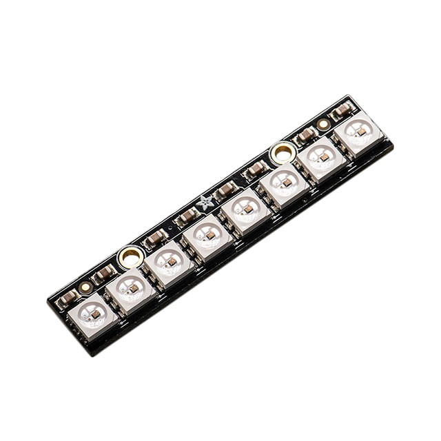
NeoPixels
terminal block - to GND on both NeoPixel strips. (black wire)
terminal block + to 5V on both NeoPixel strips. (red wire)
terminal block 21 to DIN on the first NeoPixel strip. (green wire)
terminal block 22 to DIN on the second NeoPixel strip. (green wire)
CircuitPython Usage
To use with CircuitPython, you need to first install a few libraries, into the lib folder on your board. Then you need to update code.py with the example script.
In the example below, click the Download Project Bundle button below to download the necessary libraries and the code.py file in a zip file. Extract the contents of the zip file, open the directory Sparkle_Motion_Examples/CircuitPython_Sparkle_Motion_Neopixel_Animation/ and then click on the directory that matches the version of CircuitPython you're using.
Example Code
# SPDX-FileCopyrightText: 2025 Tim Cocks for Adafruit Industries
#
# SPDX-License-Identifier: MIT
"""
Example illustrating two different LED Animations running on
Neopixels connected to 2 of the main outputs of the Sparkle Motion
"""
import board
import neopixel

from adafruit_led_animation.animation.comet import Comet
from adafruit_led_animation.animation.rainbow import Rainbow
from adafruit_led_animation.color import GREEN

strip1_pixel_pin = board.D21
strip2_pixel_pin = board.D22

pixel_count = 8

strip1_pixels = neopixel.NeoPixel(
    strip1_pixel_pin, pixel_count, brightness=0.1, auto_write=False
)
strip2_pixels = neopixel.NeoPixel(
    strip2_pixel_pin, pixel_count, brightness=0.1, auto_write=False
)

comet = Comet(strip1_pixels, speed=0.05, color=GREEN, tail_length=3, bounce=True)
rainbow = Rainbow(strip2_pixels, speed=0.05, period=3)

while True:
    comet.animate()
    rainbow.animate()
Update the /lib Folder
In the editor window in your browser, click the Open button to view the file dialog. Then, click the Upload button and select Upload Folders.
Navigate to the project bundle that you downloaded and select the /lib folder.
You'll be asked if you want to upload the /lib folder from the Project Bundle. Click Upload.
After the upload finishes, you can open the lib folder to view the two library files required for the NeoPixel examples.
Your CIRCUITPY/lib folder should contain the following folders:
adafruit_led_animation/
adafruit_pixelbuf.mpy
neopixel.mpy
In the editor window in your browser, click the Open button to view the file dialog. Then, click the Upload button and select Upload Files.
Navigate to the project bundle that you downloaded and select the code.py file.
You'll be asked if you want to overwrite the previous code.py with the new code.py file from the Project Bundle. Click OK.
This example utilizes both of the NeoPixel outputs on terminal blocks D21 and D22. It starts by initializing variables for the pixel pins and count of how many NeoPixels are in each strip. Next it creates instances of neopixel.NeoPixel for each strip. Then it creates a Comet animation on one strip, and a Rainbow animation on the other. Inside of the main while True: each animation object has it's animate() function called to advance it by one step.
IR Remote
The Adafruit Sparkle Motion has an IR Receiver built-in for all of your remote controlling needs. The Adafruit CircuitPython IRRemote library makes it easy to decode the signals sent to the receiver. This example will get you started by demonstrating how to use one of our mini remote controls to change the color and brightness of a connected strip of NeoPixels.
IR Receiver & NeoPixel Output Location
The IR Receiver is connected with the pin alias board.IR. This example assumes the NeoPixel strip will be plugged in to the terminal blocks for pin board.D21.
Necessary Hardware
You can use any IR remote with basic NEC codes that are supported by the Adafruit CircuitPython IRRemote library, and any NeoPixel strip that you like. The following items are the ones depicted on this page.
Wiring
NeoPixels
terminal block - to GND on the NeoPixel strip. (black wire)
terminal block + to 5V on the NeoPixel strip. (red wire)
terminal block 21 to DIN on the NeoPixel strip. (green wire)
CircuitPython Usage
To use with CircuitPython, you need to first install a few libraries, into the lib folder on your board. Then you need to update code.py with the example script.
In the example below, click the Download Project Bundle button below to download the necessary libraries and the code.py file in a zip file. Extract the contents of the zip file, open the directory Sparkle_Motion_Examples/CircuitPython_Sparkle_Motion_IR_Remote/ and then click on the directory that matches the version of CircuitPython you're using.
Example Code
# SPDX-FileCopyrightText: 2021 ladyada for Adafruit Industries
# SPDX-FileCopyrightText: 2025 Tim Cocks for Adafruit Industries
# SPDX-License-Identifier: MIT
"""CircuitPython Adafruit Sparkle Motion IR remote control NeoPixels example."""
import time

import board
import pulseio
from rainbowio import colorwheel

import neopixel
import adafruit_irremote

pulsein = pulseio.PulseIn(board.IR, maxlen=120, idle_state=True)
decoder = adafruit_irremote.NonblockingGenericDecode(pulsein)

IR_CODE_UP = (0, 253, 160, 95)
IR_CODE_DOWN = (0, 253, 176, 79)

IR_CODE_RIGHT = (0, 253, 80, 175)
IR_CODE_LEFT = (0, 253, 16, 239)

t0 = next_heartbeat = time.monotonic()

pixel = neopixel.NeoPixel(board.D21, 8)

brightness = 1
pixel.brightness = brightness / 10

color_number = 160
pixel.fill(colorwheel(color_number))
while True:
    for message in decoder.read():
        print(f"t={time.monotonic() - t0:.3} New IR Message")
        if isinstance(message, adafruit_irremote.IRMessage):
            if message.code == IR_CODE_UP:
                brightness = min(brightness + 1, 10)
            elif message.code == IR_CODE_DOWN:
                brightness = max(brightness - 1, 0)
            elif message.code == IR_CODE_RIGHT:
                color_number = (color_number + 32) % 256
            elif message.code == IR_CODE_LEFT:
                color_number = (color_number - 32) % 256

            pixel.brightness = brightness / 10
            pixel.fill(colorwheel(color_number))

            print("Decoded:", message.code)
            print("Brightness: ", brightness/10, " Color: ", hex(colorwheel(color_number)))
        elif isinstance(message, adafruit_irremote.NECRepeatIRMessage):
            print("NEC repeat!")
        elif isinstance(message, adafruit_irremote.UnparseableIRMessage):
            print("Failed to decode", message.reason)
        print("----------------------------")
Update the /lib Folder
In the editor window in your browser, click the Open button to view the file dialog. Then, click the Upload button and select Upload Folders.
Navigate to the project bundle that you downloaded and select the /lib folder.
You'll be asked if you want to upload the /lib folder from the Project Bundle. Click Upload.
After the upload finishes, you can open the lib folder to view the two library files required for the NeoPixel examples.
Your CIRCUITPY/lib folder should contain the following folders:
adafruit_irremote.mpy
adafruit_pixelbuf.mpy
neopixel.mpy
In the editor window in your browser, click the Open button to view the file dialog. Then, click the Upload button and select Upload Files.
Navigate to the project bundle that you downloaded and select the code.py file.
You'll be asked if you want to overwrite the previous code.py with the new code.py file from the Project Bundle. Click OK.
This example utilizes the NeoPixel output terminal blocks for pin D21. It starts by initializing PulseIn and the IR Decoder instance. Then the NeoPixel instance. Inside of the main while True: loop it reads any incoming messages from the decoder. When the up or down commands are received it raises or lowers the brightness of the NeoPixels, when the right or left commands are received it changes the color of the NeoPixels.
I2C Scan
A QT Py ESP32-S2 connected to an MCP9808 Temperature Sensor for I2C via STEMMA QT.
The I2C, or inter-integrated circuit, is a 2-wire protocol for communicating with simple sensors and devices, which means it uses two connections, or wires, for transmitting and receiving data. One connection is a clock, called SCL. The other is the data line, called SDA. Each pair of clock and data pins are referred to as a bus.
Typically, there is a device that acts as a controller and sends requests to the target devices on each bus. In this case, your microcontroller board acts as the controller, and the sensor breakout acts as the target. Historically, the controller is referred to as the master, and the target is referred to as the slave, so you may run into that terminology elsewhere. The official terminology is controller and target.
Multiple I2C devices can be connected to the same clock and data lines. Each I2C device has an address, and as long as the addresses are different, you can connect them at the same time. This means you can have many different sensors and devices all connected to the same two pins.
Both I2C connections require pull-up resistors, and most Adafruit I2C sensors and breakouts have pull-up resistors built in. If you're using one that does not, you'll need to add your own 2.2-10kΩ pull-up resistors from SCL and SDA to 3.3V.
I2C and CircuitPython
CircuitPython supports many I2C devices and makes it super simple to interact with them. There are libraries available for many I2C devices in the CircuitPython Library Bundle. (If you don't see the sensor you're looking for, keep checking back, more are being written all the time!)
In this section, you'll learn how to scan the I2C bus for all connected devices. Then you'll learn how to interact with an I2C device.
Necessary Hardware
You'll need the following additional hardware to complete the examples on this page.
While the examples here will be using the Adafruit MCP9808, a high accuracy temperature sensor, the overall process is the same for just about any I2C sensor or device.
The first thing you'll want to do is get the sensor connected so your board has I2C to talk to.
Wiring the MCP9808
The MCP9808 comes with a STEMMA QT connector, which makes wiring it up quite simple and solder-free.
Connect the STEMMA QT cable from the STEMMA QT port on your board to the STEMMA QT port on the MCP9808.
Find Your Sensor
The first thing you'll want to do after getting the sensor wired up, is make sure it's wired correctly. You're going to do an I2C scan to see if the board is detected, and if it is, print out its I2C address.
In the example below, click the Download Project Bundle button below to download the necessary libraries and the code.py file in a zip file. Extract the contents of the zip file, open the directory CircuitPython_Templates/i2c_scan/ and then click on the directory that matches the version of CircuitPython you're using.
# SPDX-FileCopyrightText: 2021 Kattni Rembor for Adafruit Industries
# SPDX-License-Identifier: MIT
"""CircuitPython I2C Device Address Scan"""
import time
import board

i2c = board.I2C()  # uses board.SCL and board.SDA
# i2c = board.STEMMA_I2C()  # For using the built-in STEMMA QT connector on a microcontroller

# To create I2C bus on specific pins
# import busio
# i2c = busio.I2C(board.GP1, board.GP0)    # Pi Pico RP2040

while not i2c.try_lock():
    pass

try:
    while True:
        print(
            "I2C addresses found:",
            [hex(device_address) for device_address in i2c.scan()],
        )
        time.sleep(2)

finally:  # unlock the i2c bus when ctrl-c'ing out of the loop
    i2c.unlock()
In the editor window in your browser, click the Open button to view the file dialog. Then, click the Upload button and select Upload Files.
Navigate to the project bundle that you downloaded and select the code.py file.
You'll be asked if you want to overwrite the previous code.py with the new code.py file from the Project Bundle. Click OK.
You'll see a new code.py file appear in the file browser. Select it and click Open to view it in the code editor.
Adafruit Sparkle Motion comes with one I2C device built in: HUSB238 power delivery chip. The I2C scan code will show the addresses from the built-in device and the MCP9808.
If you run this and it seems to hang, try manually unlocking your I2C bus by running the following two commands from the REPL.
import board
board.I2C().unlock()
First you create the i2c object, using board.I2C(). This convenience routine creates and saves a busio.I2C object using the default pins board.SCL and board.SDA. If the object has already been created, then the existing object is returned. No matter how many times you call board.I2C(), it will return the same object. This is called a singleton.
To be able to scan it, you need to lock the I2C down so the only thing accessing it is the code. So next you include a loop that waits until I2C is locked and then continues on to the scan function.
Last, you have the loop that runs the actual scan, i2c_scan(). Because I2C typically refers to addresses in hex form, the example includes this bit of code that formats the results into hex format: [hex(device_address) for device_address in i2c.scan()].
Open the serial console to see the results! The code prints out an array of addresses. You've connected the MCP9808 which has a 7-bit I2C address of 0x18. The result for this sensor is I2C addresses found: ['0x18']. If no addresses are returned, refer back to the wiring diagrams to make sure you've wired up your sensor correctly.
WiFi Test
In this example, you'll test your Sparkle Motion WiFi connection by connecting to your SSID, printing your MAC address and IP address to the REPL and then pinging Google.
settings.toml File
If you've worked on WiFi projects with CircuitPython before, you're probably familiar with the secrets.py file. This file is a Python file that is stored on your CIRCUITPY drive that contains all of your secret WiFi information, such as your SSID, SSID password and any API keys for IoT services.
As of CircuitPython 8, there is support for a settings.toml file. Similar to secrets.py, the settings.toml file separates your sensitive information from your main code.py file.
Your settings.toml file should be stored in the main directory of your board. It should not be in a folder.
settings.toml File Example
Here is an example on how to format your settings.toml file.
# Comments are supported
CIRCUITPY_WIFI_SSID="guest wifi"
CIRCUITPY_WIFI_PASSWORD="guessable"
CIRCUITPY_WEB_API_PORT=80
CIRCUITPY_WEB_API_PASSWORD="passw0rd"
test_variable="this is a test"
thumbs_up="\U0001f44d"
In a settings.toml file, it's important to keep these factors in mind:
Strings are wrapped in double quotes; ex: "your-string-here"
Integers are not quoted and may be written in decimal with optional sign (+1, -1, 1000) or hexadecimal (0xabcd).
Floats, octal (0o567) and binary (0b11011) are not supported.
Use \u escapes for weird characters, \x and \ooo escapes are not available in .toml files
Example: \U0001f44d for 👍 (thumbs up emoji) and \u20ac for € (EUR sign)
Unicode emoji, and non-ASCII characters, stand for themselves as long as you're careful to save in "UTF-8 without BOM" format
When your settings.toml file is ready, you can save it in your text editor with the .toml extension.
CircuitPython WiFi Example
In the example below, click the Download Project Bundle button below to download the code.py file in a zip file. Extract the contents of the zip file and then click on the directory that matches the version of CircuitPython you're using.
# SPDX-FileCopyrightText: 2022 Liz Clark for Adafruit Industries
#
# SPDX-License-Identifier: MIT

from os import getenv
import ipaddress
import wifi
import socketpool

# Get WiFi details, ensure these are setup in settings.toml
ssid = getenv("CIRCUITPY_WIFI_SSID")
password = getenv("CIRCUITPY_WIFI_PASSWORD")

if None in [ssid, password]:
    raise RuntimeError(
        "WiFi settings are kept in settings.toml, "
        "please add them there. The settings file must contain "
        "'CIRCUITPY_WIFI_SSID', 'CIRCUITPY_WIFI_PASSWORD', "
        "at a minimum."
    )

print()
print("Connecting to WiFi")

#  connect to your SSID
try:
    wifi.radio.connect(ssid, password)
except TypeError:
    print("Could not find WiFi info. Check your settings.toml file!")
    raise

print("Connected to WiFi")

pool = socketpool.SocketPool(wifi.radio)

#  prints MAC address to REPL
print("My MAC addr:", [hex(i) for i in wifi.radio.mac_address])

#  prints IP address to REPL
print(f"My IP address is {wifi.radio.ipv4_address}")

#  pings Google
ipv4 = ipaddress.ip_address("8.8.4.4")
print("Ping google.com: %f ms" % (wifi.radio.ping(ipv4)*1000))
In the editor window in your browser, click the Open button to view the file dialog. Then, click the Upload button and select Upload Files.
Navigate to the project bundle that you downloaded and select the code.py file.
You'll be asked if you want to overwrite the previous code.py with the new code.py file from the Project Bundle. Click OK.
Update Your settings.toml File
Remember to add your settings.toml file as described earlier in this page. You'll need to include your CIRCUITPY_WIFI_SSID and CIRCUITPY_WIFI_PASSWORD in the file.
You can edit the file manually in the USB code editor by clicking Open, selecting settings.toml and clicking Open at the bottom of the dialog box.
With settings.toml open in the editor, you can add your WiFi credentials:
CIRCUITPY_WIFI_SSID = "your-ssid-here"
CIRCUITPY_WIFI_PASSWORD = "your-ssid-password-here"
Once your credentials are entered, click Save above the editor to save your changes to settings.toml.
Once everything is saved to the board, Restart the Serial Console to see the data printed out!
How the CircuitPython WiFi Example Works
In the basic WiFi test, the board connects to your SSID by importing your SSID and SSID password from the settings.toml file.
wifi.radio.connect(os.getenv('CIRCUITPY_WIFI_SSID'), os.getenv('CIRCUITPY_WIFI_PASSWORD'))Then, your MAC address and IP address are printed to the REPL.
#  prints MAC address to REPL
print("My MAC addr:", [hex(i) for i in wifi.radio.mac_address])

#  prints IP address to REPL
print("My IP address is", wifi.radio.ipv4_address)Finally, google.com is pinged. The amount of time it takes to ping is printed to the REPL and the code stops running.
#  pings Google
ipv4 = ipaddress.ip_address("8.8.4.4")
print("Ping google.com: %f ms" % (wifi.radio.ping(ipv4)*1000))
By successfully running this WiFi test code, you can confirm that your board is connecting to WiFi with CircuitPython successfully and you can move on to more advanced projects.
Adafruit IO
Adafruit IO gives you the option to disconnect your microcontroller from your computer and run it off of USB power or a battery, and still be able to see the data. It also allows you to send data to your microcontroller, such as NeoPixel colors. This example shows how to both send data to and receive data from Adafruit IO. It pulls from a "random" number generator and sends the "random" number to Adafruit IO, while simultaneously listening for NeoPixel color data from Adafruit IO.
NeoPixel Location
Adafruit IO Feeds and Dashboard
The first thing you'll need to do, is head over to Adafruit IO and make sure your account is set up.
Then, you need to create two feeds called neopixel and random. These are case sensitive!
Next, you'll create a dashboard for the NeoPixel Color Picker. You can name the dashboard whatever you like.
Once the dashboard is created, you'll want to add a color picker block. The color picker block is highlighted by a red arrow in the image below.
Once you choose the color picker block, you'll need to connect a feed to it. Check the box next to neopixel.
Finally, a Block Settings page will come up. You can add an optional block title here. Then you press Create Block.
The dashboard should look something like the following.
Now that things are set up on the Adafruit IO end, you can continue on to the code on your microcontroller!
Adafruit IO settings.toml
This example requires you to provide your Wi-Fi credentials, and your Adafruit IO username and key. To do this, you'll want to create a settings.toml file on your CIRCUITPY drive.
To obtain your Adafruit IO key, follow the initial steps on this page.
Your settings.toml file should be structured in a certain way and contain all the necessary information. Follow these instructions to create your settings.toml file.
Adafruit IO Example Code
To run this example, you need to first install the NeoPixel, Adafruit IO, and Adafruit MiniMQTT libraries into the lib folder on your board. Then you need to update code.py with the example script.
In the example below, click the Download Project Bundle button below to download the necessary libraries and the code.py file in a zip file. Extract the contents of the zip file. You'll see a code.py file and /lib folder.
# SPDX-FileCopyrightText: 2021 Ladyada for Adafruit Industries
# SPDX-FileCopyrightText: 2022 Kattni Rembor for Adafruit Industries
# SPDX-License-Identifier: MIT
import time
import ssl
import os
from random import randint
import microcontroller
import socketpool
import wifi
import board
import neopixel
import adafruit_minimqtt.adafruit_minimqtt as MQTT
from adafruit_io.adafruit_io import IO_MQTT


# WiFi
try:
    print("Connecting to %s" % os.getenv("CIRCUITPY_WIFI_SSID"))
    wifi.radio.connect(os.getenv("CIRCUITPY_WIFI_SSID"), os.getenv("CIRCUITPY_WIFI_PASSWORD"))
    print("Connected to %s!" % os.getenv("CIRCUITPY_WIFI_SSID"))
# Wi-Fi connectivity fails with error messages, not specific errors, so this except is broad.
except Exception as e:  # pylint: disable=broad-except
    print("Failed to connect to WiFi. Error:", e, "\nBoard will hard reset in 30 seconds.")
    time.sleep(30)
    microcontroller.reset()

# Initialise NeoPixel
pixel = neopixel.NeoPixel(board.NEOPIXEL, 1, brightness=0.3)


# Define callback functions which will be called when certain events happen.
def connected(client):
    print("Connected to Adafruit IO!  Listening for NeoPixel changes...")
    # Subscribe to Adafruit IO feed called "neopixel"
    client.subscribe("neopixel")


def message(client, feed_id, payload):  # pylint: disable=unused-argument
    print("Feed {0} received new value: {1}".format(feed_id, payload))
    if feed_id == "neopixel":
        pixel.fill(int(payload[1:], 16))


# Create a socket pool
pool = socketpool.SocketPool(wifi.radio)

# Initialize a new MQTT Client object
mqtt_client = MQTT.MQTT(
    broker="io.adafruit.com",
    username=os.getenv("ADAFRUIT_AIO_USERNAME"),
    password=os.getenv("ADAFRUIT_AIO_KEY"),
    socket_pool=pool,
    ssl_context=ssl.create_default_context(),
)

# Initialize Adafruit IO MQTT "helper"
io = IO_MQTT(mqtt_client)

# Set up the callback methods above
io.on_connect = connected
io.on_message = message

timestamp = 0
while True:
    try:
        # If Adafruit IO is not connected...
        if not io.is_connected:
            # Connect the client to the MQTT broker.
            print("Connecting to Adafruit IO...")
            io.connect()

        # Explicitly pump the message loop.
        io.loop()
        # Obtain the "random" value, print it and publish it to Adafruit IO every 10 seconds.
        if (time.monotonic() - timestamp) >= 10:
            random_number = "{}".format(randint(0, 255))
            print("Current 'random' number: {}".format(random_number))
            io.publish("random", random_number)
            timestamp = time.monotonic()

    # Adafruit IO fails with internal error types and WiFi fails with specific messages.
    # This except is broad to handle any possible failure.
    except Exception as e:  # pylint: disable=broad-except
        print("Failed to get or send data, or connect. Error:", e,
              "\nBoard will hard reset in 30 seconds.")
        time.sleep(30)
        microcontroller.reset()
Update the /lib Folder
In the editor window in your browser, click the Open button to view the file dialog. Then, click the Upload button and select Upload Folders.
Navigate to the project bundle that you downloaded and select the /lib folder.
You'll be asked if you want to upload the /lib folder from the Project Bundle. Click Upload.
After the upload finishes, you can open the lib folder to view the library files required for the Adafruit IO example.
Update code.py
In the editor window in your browser, click the Open button to view the file dialog. Then, click the Upload button and select Upload Files.
Navigate to the project bundle that you downloaded and select the code.py file.
You'll be asked if you want to overwrite the previous code.py with the new code.py file from the Project Bundle. Click OK.
Update Your settings.toml File
Remember to add your settings.toml file as described earlier in this page. You'll need to include, your ADAFRUIT_AIO_USERNAME, ADAFRUIT_AIO_KEY, CIRCUITPY_WIFI_SSID and CIRCUITPY_WIFI_PASSWORD in the file.
You can edit the file manually in the USB code editor by clicking Open, selecting settings.toml and clicking Open at the bottom of the dialog box.
With settings.toml open in the editor, you can add your WiFi and Adafruit IO credentials:
CIRCUITPY_WIFI_SSID = "your-ssid-here"
CIRCUITPY_WIFI_PASSWORD = "your-ssid-password-here"
ADAFRUIT_AIO_USERNAME = "your-aio-username-here"
ADAFRUIT_AIO_KEY = "your-aio-key-here"
Once your credentials are entered, click Save above the editor to save your changes to settings.toml.
Once everything is saved to the board, Restart the Serial Console to run the new code.py. You'll see the connection info and current readings printed out in the console.
NeoPixel Color Change
To change the color of the NeoPixel, go to the NeoPixel Adafruit IO dashboard you created at the beginning, and click on the colored circle in the ColorPicker block. It will bring up the following.
You can move the dot in the box around, and the slider line across the gradient to choose the perfect color. Choose a new color and click SAVE.
The NeoPixel color will update, and you will see the new value printed to the serial console, as shown below.
Code Walkthrough
This example contains three try/except blocks. These are included where the code is likely to fail due to WiFi or Adafruit IO connection failures. WiFi can be finicky, and without these code blocks, if the connection was lost, the code would crash. Instead, it is designed to reset the board and start the code over again to reestablish the connection, regardless of the cause. This ensures your code will continue running. The details of these blocks are explained below.
First you import all of the necessary modules and libraries.
import time
import ssl
import os
from random import randint
import socketpool
import wifi
import board
import neopixel
import adafruit_minimqtt.adafruit_minimqtt as MQTT
from adafruit_io.adafruit_io import IO_MQTT
Note that if a settings.toml file is not present on your CIRCUITPY drive, the code will fail to run, and you will receive an error in the serial console. Add a settings.toml file to your CIRCUITPY drive to resolve this error.
The WiFi attempts to connect and prints the status to the serial console. If it connects successfully, the code continues onto the NeoPixel set up.
try:
    print("Connecting to %s" % os.getenv("CIRCUITPY_WIFI_SSID"))
    wifi.radio.connect(os.getenv("CIRCUITPY_WIFI_SSID"), os.getenv("CIRCUITPY_WIFI_PASSWORD"))
    print("Connected to %s!" % os.getenv("CIRCUITPY_WIFI_SSID"))
If the WiFi connection is not successful, the error will be printed to the serial console, and the board will hard reset after 30 seconds.
except Exception as e:  # pylint: disable=broad-except
    print("Failed to connect to WiFi. Error:", e, "\nBoard will hard reset in 30 seconds.")
    time.sleep(30)
    microcontroller.reset()
Once the WiFi successfully connects, the NeoPixel object is initiated.
pixel = neopixel.NeoPixel(board.NEOPIXEL, 1, brightness=0.3)
Following that are two callback methods. For more details, check out this guide. The connected method subscribes to the NeoPixel feed on Adafruit IO. The message callback checks for updates to the NeoPixel feed and turns the pixel the color from the feed.
def connected(client):
    print("Connected to Adafruit IO!  Listening for NeoPixel changes...")
    # Subscribe to Adafruit IO feed called "neopixel"
    client.subscribe("neopixel")


# pylint: disable=unused-argument
def message(client, feed_id, payload):
    print("Feed {0} received new value: {1}".format(feed_id, payload))
    if feed_id == "neopixel":
pixel.fill(int(payload[1:], 16))You create a socket pool, use that to initialise the new MQTT Client object, and use that to initialise the Adafruit IO MQTT "helper".
pool = socketpool.SocketPool(wifi.radio)

mqtt_client = MQTT.MQTT(
    broker="io.adafruit.com",
    username=os.getenv("ADAFRUIT_AIO_USERNAME"),
    password=os.getenv("ADAFRUIT_AIO_KEY"),
    socket_pool=pool,
    ssl_context=ssl.create_default_context(),
)

io = IO_MQTT(mqtt_client)
You set up the callback methods mentioned above.
io.on_connect = connected
io.on_message = message
Next, you attempt to connect the client to the MQTT broker. If connection is successful, the code continues on to the timestamp.
try:
    io.connect()
If the MQTT broker connection is not successful, the error is printed to the serial console, and the board will hard reset after 30 seconds.
except Exception as e:
    print("Failed to connect to Adafruit IO. Error:", e, "\nBoard will hard reset in 30 seconds.")
    time.sleep(30)
    microcontroller.reset()
Once the broker is connected, you set the timestamp to 0 immediately before the loop.
timestamp = 0
Inside the loop, you attempt to do two things. You first explicitly poll the message loop. Check out this guide for more details on that.
while True:
    try:
        io.loop()
Second, you have a block of code that runs every 10 seconds. Inside, you obtain a "random" value between 0-255 inclusive, print it to the serial console, and publish it to an Adafruit IO feed. Finally, you reset timestamp, so the block of code knows when another 10 seconds has passed and runs again.
[...]
        if (time.monotonic() - timestamp) >= 10:
            random_number = "{}".format(randint(0, 255))
            print("Current 'random' number: {}".format(random_number))
            io.publish("random", random_number)
timestamp = time.monotonic()If at any time WiFi or Adafruit IO disconnects, the code will print the error to the serial console, and the board will hard reset after 30 seconds.
[...]
    except Exception as e:
        print("Failed to get or send data, or connect. Error:", e,
              "\nBoard will hard reset in 30 seconds.")
        time.sleep(30)
        microcontroller.reset()
That's all there is to using CircuitPython and Adafruit IO to send data to Adafruit IO and receive data from it!
Arduino IDE Setup
On macOS, you need to use this board with a hub and USB A to USB C cable to upload any software. If you plug the board directly into a USB C port on your Mac, it will assume it needs power delivery (PD) and the USB to Serial port will not work.
We primarily recommend using the ESP32 chipsets with Arduino. Don't forget you will also need to install the SiLabs CP2104 Driver if you are using an ESP32 board with USB-to-Serial converter! (There's no harm in doing it, so we recommend even if you aren't.)
Install Arduino IDE
The first thing you will need to do is to download the latest release of the Arduino IDE. You will need to be using version 1.8 or higher for this guide.
Install CP2104 / CP2102N USB Driver
Many ESP32 boards have a USB-to-Serial converter that talks to the chip itself and will need a driver on your computer's operating system. The driver is available for Mac and Windows. It is already built into Linux.
Click here to download the CP2104 USB Driver
Install CH9102 / CH34X USB Driver
Newer ESP32 boards have a different USB-to-serial converter that talks to the chip itself and will need a driver on your computer's operating system. The driver is available for Mac and Windows. It is already built into Linux.
If you would like more detail, check out the guide on installing these drivers.
Click here to download the Windows driver
Click here to download the Mac driver
Install ESP32 Board Support Package from GitHub
For this board, we recommend you don't use 'release' version of Espressif's board support package because the current release doesn't include board support.
Instead, we will install the "very latest" by following these instructions (scroll down for mac and Linux as well.
Basically, install by git cloneing the Espressif ESP32 board support to get the very latest version of the code.
In the Tools → Board submenu you should see ESP32 Arduino (in sketchbook) and in that dropdown it should contain the ESP32 boards along with all the latest ESP32 boards.
Look for the board called Adafruit Sparkle Motion (ESP32).
The upload speed can be changed: faster speed makes uploads take less time but sometimes can cause upload issues. 921600 should work fine, but if you're having issues, you can drop down lower.
Blink
The first and most basic program you can upload to your Arduino is the classic Blink sketch. This takes something on the board and makes it, well, blink! On and off. It's a great way to make sure everything is working and you're uploading your sketch to the right board and right configuration.
When all else fails, you can always come back to Blink!
On macOS, you need to use this board with a hub and USB A to USB C cable to upload any software. If you plug the board directly into a USB C port on your Mac, it will assume it needs power delivery (PD) and the USB to Serial port will not work.
Pre-Flight Check: Get Arduino IDE & Hardware Set Up
This lesson assumes you have Arduino IDE set up. This is a generalized checklist; some elements may not apply to your hardware. If you haven't yet, check the previous steps in the guide to make sure you:
Install the very latest Arduino IDE for Desktop (not all boards are supported by the Web IDE, so we don't recommend it)
Install any board support packages (BSP) required for your hardware. Some boards are built in defaults on the IDE, but lots are not! You may need to install plug-in support which is called the BSP.
Get a Data/Sync USB cable for connecting your hardware. A significant amount of problems folks have stem from not having a USB cable with data pins. Yes, these cursed cables roam the land, making your life hard. If you find a USB cable that doesn't work for data/sync, throw it away immediately! There is no need to keep it around, cables are very inexpensive these days.
Install any drivers required - If you have a board with a FTDI or CP210x chip, you may need to get separate drivers. If your board has native USB, it probably doesn't need anything. After installing, reboot to make sure the driver sinks in.
Connect the board to your computer. If your board has a power LED, make sure its lit. Is there a power switch? Make sure it’s turned On!
Startup Arduino IDE and Select Board/Port
OK now you are prepared! Open the Arduino IDE on your computer. Now you have to tell the IDE what board you are using, and how you want to connect to it.
In the IDE find the Tools menu. You will use this to select the board. If you switch boards, you must switch the selection! So always double-check before you upload code in a new session.
New Blink Sketch
OK let’s make a new blink sketch! From the File menu, select New.
Then in the new window, copy and paste this text:
int led = LED_BUILTIN;

void setup() {
  // Some boards work best if we also make a serial connection
  Serial.begin(115200);

  // set LED to be an output pin
  pinMode(led, OUTPUT);
}

void loop() {
  // Say hi!
  Serial.println("Hello!");

  digitalWrite(led, HIGH);   // turn the LED on (HIGH is the voltage level)
  delay(500);                // wait for a half second
  digitalWrite(led, LOW);    // turn the LED off by making the voltage LOW
  delay(500);                // wait for a half second
}
Note that in this example, we are not only blinking the LED but also printing to the Serial monitor, think of it as a little bonus to test the serial connection.
One note you'll see is that we reference the LED with the constant LED_BUILTIN rather than a number. That's because, historically, the built in LED was on pin 13 for Arduinos. But in the decades since, boards don't always have a pin 13, or maybe it could not be used for an LED. So, the LED could have moved to another pin. It's best to use LED_BUILTIN so you don't get the pin number confused!
Verify (Compile) Sketch
OK now you can click the Verify button to convert the sketch into binary data to be uploaded to the board.
Note that verifying a sketch is the same as Compiling a sketch - so we will use the words interchangeably.
During verification/compilation, the computer will do a bunch of work to collect all the libraries and code, and the results will appear in the bottom window of the IDE.
If something went wrong with compilation, you would get red warning/error text in the bottom window letting you know what the error was. It will also highlight the line with an error.
For example, here I had the wrong board selected - and the selected board does not have a built in LED!
Here's another common error, in my haste I forgot to add a ; at the end of a line. The compiler warns me that it's looking for one - note that the error is actually a few lines up!
Turning on detailed compilation warnings and output can be very helpful sometimes - It’s in Preferences under "Show Verbose Output During:" and check the Compilation button. If you ever need to get help from others, be sure to do this and then provide all the text that is output. It can assist in nailing down what happened!
On success you will see something like this white text output and the message Done compiling. in the message area.
Upload Sketch
Once the code is verified/compiling cleanly you can upload it to your board. Click the Upload button.
The IDE will try to compile the sketch again for good measure, then it will try to connect to the board and upload the file.
This is actually one of the hardest parts for beginners because it's where a lot of things can go wrong.
However, let’s start with what it looks like on success! Here's what your board upload process looks like when it goes right:
Often times you will get a warning like this, which is kind of vague:
No device found on COM66 (or whatever port is selected)
An error occurred while uploading the sketch
This could be a few things.
First up, check again that you have the correct board selected! Many electronics boards have very similar names or look, and often times folks grab a board different from what they thought.
Second, make sure you selected the right port! If you have the wrong port or no port selected, Arduino doesn't know where to look for your board.
If both of those are correct, the next step is to enable verbose upload messages.
Before continuing we really really suggest turning on Verbose Upload messages, it will help in this process because you will be able to see what the IDE is trying to do. It's a checkbox in the Preferences menu.
Now you can try uploading again!
This time, you should have success!
After uploading this way, be sure to click the reset button - it sort of makes sure that the board got a good reset and will come back to life nicely.
Finally, a Blink!
OK it was a journey but now we're here and you can enjoy your blinking LED. Next up, try to change the delay between blinks and re-upload. It's a good way to make sure your upload process is smooth and practiced.
Built-In NeoPixel
Your board has a built-in RGB NeoPixel status LED. You can use Arduino code to control the color and brightness of this LED. It is also used to indicate the bootloader status.
A NeoPixel is what Adafruit calls the WS281x family of addressable RGB LEDs. It contains three LEDs - a red one, a green one and a blue one - alongside a driver chip in a tiny package controlled by a single pin. They can be used individually (as in the built-in LED on your board) or chained together in strips or other creative form factors. NeoPixels do not light up on their own; they require a microcontroller. So, it's super convenient that the NeoPixel is built into your microcontroller board!
This page will cover using Arduino to control the status RGB NeoPixel built into your microcontroller. Time to get started!
NeoPixel Location
Arduino Library Installation
You can install the necessary libraries from the Library Manager. To open, click Sketch > Include Library > Manage Libraries...
Search for NeoPixel and install the Adafruit NeoPixel library.
There are no additional library dependencies for the Adafruit NeoPixel library.
Rainbow Swirl Demo
// SPDX-FileCopyrightText: 2024 ladyada for Adafruit Industries
//
// SPDX-License-Identifier: MIT

#include <Adafruit_NeoPixel.h>

#define NUMPIXELS 1
Adafruit_NeoPixel pixel(NUMPIXELS, PIN_NEOPIXEL, NEO_GRB + NEO_KHZ800);

void setup() {
  Serial.begin(115200);

  pixel.begin();
  pixel.setBrightness(25);
  pixel.show();

}

uint16_t firstPixelHue = 0;

void loop() {
  firstPixelHue += 256;
  for(int i=0; i<pixel.numPixels(); i++) {
      int pixelHue = firstPixelHue + (i * 65536L / pixel.numPixels());
      pixel.setPixelColor(i, pixel.gamma32(pixel.ColorHSV(pixelHue)));
    }
  pixel.show();

  delay(10);

}
Upload the sketch to your board. You'll see the onboard NeoPixel run through a looping rainbow animation.
Arduino Sparkle Motion Demo
The main use of the Sparkle Motion is lighting up RGB LEDs to dazzle and delight. Using the Sparkle Motion with Arduino involves installing the Adafruit_NeoPixel library and running the provided example code. In the example below, you'll attach two NeoPixel strips to the Sparkle Motion Mini and see how you can write code to run two different LED animations on two strips of NeoPixels at the same time.
Wiring
NeoPixels
terminal block - to GND on both NeoPixel strips. (black wire)
terminal block + to 5V on both NeoPixel strips. (red wire)
terminal block 21 to DIN on the first NeoPixel strip. (green wire)
terminal block 22 to DIN on the second NeoPixel strip. (green wire)
Library Installation
You can install the Adafruit NeoPixel library for Arduino using the Library Manager in the Arduino IDE.
Click the Manage Libraries ... menu item, search for Adafruit NeoPixel and select the Adafruit NeoPixel library:
No additional dependencies are required for the NeoPixel library.
Example Code
// SPDX-FileCopyrightText: 2025 Liz Clark for Adafruit Industries
//
// SPDX-License-Identifier: MIT

#include <Adafruit_NeoPixel.h>

#define BLOCK_1 21
#define BLOCK_2 22
#define NUM_PIXELS 8

Adafruit_NeoPixel STRIP_1(NUM_PIXELS, BLOCK_1, NEO_GRB + NEO_KHZ800);
Adafruit_NeoPixel STRIP_2(NUM_PIXELS, BLOCK_2, NEO_GRB + NEO_KHZ800);

void setup() {
  STRIP_1.begin();
  STRIP_2.begin();
  STRIP_1.setBrightness(25);
  STRIP_2.setBrightness(50);
}

uint16_t pixelHue_1 = 0;
uint16_t pixelHue_2 = 256;

void loop() {
  pixelHue_1 += 256;
  for(int i=0; i<STRIP_1.numPixels(); i++) {
      int hue_1 = pixelHue_1 + (i * 65536L / STRIP_1.numPixels());
      STRIP_1.setPixelColor(i, STRIP_1.gamma32(STRIP_1.ColorHSV(hue_1)));
    }
  STRIP_1.show();

  pixelHue_2 -= 256;
  for(int i=STRIP_2.numPixels(); i>-1; i--) {
      int hue_2 = pixelHue_2 + (i * 65536L / STRIP_2.numPixels());
      STRIP_2.setPixelColor(i, STRIP_2.gamma32(STRIP_2.ColorHSV(hue_2)));
    }
  STRIP_2.show();

  delay(10);

}
Upload the example code to the Sparkle Motion. You'll see both strips cycle through the rainbow swirl, but in a different order on each strip.
Arduino IR Remote
The Adafruit Sparkle Motion has an IR Receiver built-in for all of your remote controlling needs. The IRremote library makes it easy to decode the signals sent to the receiver. This example will get you started by demonstrating how to use one of our mini remote controls to change the color and brightness of a connected strip of NeoPixels.
IR Receiver & NeoPixel Output Location
The IR Receiver is connected to pin 32. This example assumes the NeoPixel strip will be plugged in to the terminal blocks for pin 21.
Necessary Hardware
You'll need an IR remote that uses one of the protocols supported by the IRremote library, and any strip of NeoPixels. The following items are the ones depicted on this page.
Wiring
NeoPixels
terminal block - to GND on the NeoPixel strip. (black wire)
terminal block + to 5V on the NeoPixel strip. (red wire)
terminal block 21 to DIN on the NeoPixel strip. (green wire)
Library Installation
You can install the Adafruit NeoPixel, and IRremote libraries for Arduino using the Library Manager in the Arduino IDE.
Click the Manage Libraries ... menu item, search for Adafruit NeoPixel and click the Install button on the Adafruit NeoPixel result:
Next, search for IRremote and click the install button on the IRremote result:
No additional dependencies are required for the NeoPixel or IRremote libraries.
Example Code
// SPDX-FileCopyrightText: 2024 Liz Clark for Adafruit Industries
// SPDX-FileCopyrightText: 2025 Tim Cocks for Adafruit Industries
//
// SPDX-License-Identifier: MIT

/*
 * Based on the SimpleReceiver.cpp and SimpleSender.cpp from the
 * Arduino-IRremote https://github.com/Arduino-IRremote/Arduino-IRremote.
 * by Armin Joachimsmeyer
 ************************************************************************************
 * MIT License
 *
 * Copyright (c) 2020-2023 Armin Joachimsmeyer
 *
 */

#include <Arduino.h>

#include <IRremote.hpp> // include the library
#include <Adafruit_NeoPixel.h>

#define NEOPIXEL_STRIP_PIN 21
#define NUM_PIXELS 8

#define IR_RECEIVE_PIN   32

Adafruit_NeoPixel NEOPIXEL_STRIP(NUM_PIXELS, NEOPIXEL_STRIP_PIN, NEO_GRB + NEO_KHZ800);

uint8_t upCmd = 0x5;
uint8_t downCmd = 0xD;
uint8_t rightCmd = 0xA;
uint8_t leftCmd = 0x8;

uint16_t pixelHue = 0;
uint8_t brightness = 25;

void setup() {
    Serial.begin(115200);
    while (!Serial)
        ;
    Serial.println("Adafruit Sparkle Motion IR Remote Control NeoPixels Demo");
    IrReceiver.begin(IR_RECEIVE_PIN);
    Serial.print("IRin on pin ");
    Serial.print(IR_RECEIVE_PIN);
    NEOPIXEL_STRIP.begin();
    NEOPIXEL_STRIP.setBrightness(25);
}

void loop() {
    /*
     * Check if received data is available and if yes, try to decode it.
     * When left or right buttons are pressed, change the pixelHue.
     * When up or down buttons are pressed, change the brightness.
     */
    if (IrReceiver.decode()) {
        if (IrReceiver.decodedIRData.protocol == UNKNOWN) {
            Serial.println("unknown");
            IrReceiver.printIRResultRawFormatted(&Serial, true);
            IrReceiver.resume();
        } else {
            IrReceiver.resume();
            //IrReceiver.printIRResultShort(&Serial);

            // Ignore repeat codes from holding down the button
            if (IrReceiver.decodedIRData.flags == 0){
              //Serial.printf("Command: %d\n",IrReceiver.decodedIRData.command);
              if (IrReceiver.decodedIRData.command == upCmd){
                Serial.println("UP btn");
                brightness = min(brightness + 25, 255);
              }else if (IrReceiver.decodedIRData.command == downCmd){
                Serial.println("DOWN btn");
                brightness = max(brightness - 25, 0);
              }else if (IrReceiver.decodedIRData.command == leftCmd){
                Serial.println("LEFT btn");
                pixelHue = (pixelHue - 8192) % 65536;
              }else if (IrReceiver.decodedIRData.command == rightCmd){
                Serial.println("RIGHT btn");
                pixelHue = (pixelHue + 8192) % 65536;
              }

              NEOPIXEL_STRIP.setBrightness(brightness);
              NEOPIXEL_STRIP.fill(NEOPIXEL_STRIP.gamma32(NEOPIXEL_STRIP.ColorHSV(pixelHue)));
              NEOPIXEL_STRIP.show();
              delay(100);
            }
        }
        Serial.println();
    }
}
Once the code is running, press the up and down arrow keys on the remote to increase and decrease the brightness. Press the left and right arrow keys to cycle through the available colors forward or backward.
I2C
A lot of sensors, displays, and devices can connect over I2C. I2C is a 2-wire 'bus' that allows multiple devices to all connect on one set of pins so it's very convenient for wiring!
When using your board, you'll probably want to connect up I2C devices, and it can be a little tricky the first time. The best way to debug I2C is go through a checklist and then perform an I2C scan.
Common I2C Connectivity Issues
Have you connected four wires (at a minimum) for each I2C device? Power the device with whatever is the logic level of your microcontroller board (probably 3.3V), then a ground wire, and a SCL clock wire, and a SDA data wire.
If you're using a STEMMA QT board - check if the power LED is lit. It's usually a green LED to the left side of the board.
Does the STEMMA QT/I2C port have switchable power or pullups? To reduce power, some boards have the ability to cut power to I2C devices or the pullup resistors. Check the documentation if you have to do something special to turn on the power or pullups.
If you are using a DIY I2C device, do you have pullup resistors? Many boards do not have pullup resistors built in and they are required! We suggest any common 2.2K to 10K resistors. You'll need two: one each connects from SDA to positive power, and SCL to positive power. Again, positive power (a.k.a VCC, VDD or V+) is often 3.3V.
Do you have an address collision? You can only have one board per address. So, you cannot, say, connect two AHT20's to one I2C port because they have the same address and will interfere. Check the sensor or documentation for the address. Sometimes there are ways to adjust the address.
Does your board have multiple I2C ports? Historically, boards only came with one. But nowadays you can have two or even three! This can help solve the "hey, but what if I want two devices with the same address" problem: just put one on each bus.
Are you hot-plugging devices? I2C does not support dynamic re-connection, you cannot connect and disconnect sensors as you please. They should all be connected on boot and not change. (Only exception is if you're using a hot-plug assistant but that'll cost you).
Are you keeping the total bus length reasonable? I2C was designed for maybe 6" max length. We like to push that with plug-n-play cables, but really please keep them as short as possible! (Only exception is if you're using an active bus extender).
Built-in I2C Device
The Adafruit Sparkle Motion has one built-in device connected to the I2C bus, a HUSB238 power delivery chip using address 0x8.
Perform an I2C scan!
Install TestBed Library
To scan I2C, the Adafruit TestBed library is used. This library and example just make the scan a little easier to run because it takes care of some of the basics. You will need to add support by installing the library. Good news: it is very easy to do it. Go to the Arduino Library Manager.
Search for TestBed and install the Adafruit TestBed library.
Now open up the I2C Scan example
// SPDX-FileCopyrightText: 2023 Carter Nelson for Adafruit Industries
//
// SPDX-License-Identifier: MIT
// --------------------------------------
// i2c_scanner
//
// Modified from https://playground.arduino.cc/Main/I2cScanner/
// --------------------------------------

#include <Wire.h>

// Set I2C bus to use: Wire, Wire1, etc.
#define WIRE Wire

void setup() {
  WIRE.begin();

  Serial.begin(9600);
  while (!Serial)
     delay(10);
  Serial.println("\nI2C Scanner");
}


void loop() {
  byte error, address;
  int nDevices;

  Serial.println("Scanning...");

  nDevices = 0;
  for(address = 1; address < 127; address++ )
  {
    // The i2c_scanner uses the return value of
    // the Write.endTransmisstion to see if
    // a device did acknowledge to the address.
    WIRE.beginTransmission(address);
    error = WIRE.endTransmission();

    if (error == 0)
    {
      Serial.print("I2C device found at address 0x");
      if (address<16)
        Serial.print("0");
      Serial.print(address,HEX);
      Serial.println("  !");

      nDevices++;
    }
    else if (error==4)
    {
      Serial.print("Unknown error at address 0x");
      if (address<16)
        Serial.print("0");
      Serial.println(address,HEX);
    }
  }
  if (nDevices == 0)
    Serial.println("No I2C devices found\n");
  else
    Serial.println("done\n");

  delay(5000);           // wait 5 seconds for next scan
}
Wire up I2C device
While the examples here will be using the Adafruit MCP9808, a high accuracy temperature sensor, the overall process is the same for just about any I2C sensor or device.
The first thing you'll want to do is get the sensor connected so your board has I2C to talk to.
Wiring the MCP9808
The MCP9808 comes with a STEMMA QT connector, which makes wiring it up quite simple and solder-free.
Connect the STEMMA QT cable from the STEMMA QT port on the Sparkle Motion to the STEMMA QT port on the MCP9808.
Now upload the scanning sketch to your microcontroller and open the serial port to see the output. You should see something like this:
I2S Mic
You can use the onboard I2S microphone with the built-in I2S library in the espressif board support package. The I2S microphone is connected to the following pins on the Sparkle Motion:
BCLK: 26
WS: 33
DATA_IN: 25
The example below will plot samples from the mic to the plotter inside the Arduino IDE.
No additional libraries need to be installed for this example - the I2S library is included in the Espressif board support package.
Example Code
// SPDX-FileCopyrightText: 2025 Limor Fried for Adafruit Industries
//
// SPDX-License-Identifier: MIT

#include <Arduino.h>
#include "ESP_I2S.h"

// I2S pin definitions for Sparklemotion
const uint8_t I2S_SCK = 26;  // BCLK
const uint8_t I2S_WS = 33;   // LRCLK
const uint8_t I2S_DIN = 25;  // DATA_IN

// Create I2S instance
I2SClass i2s;

void setup() {
  // Fast serial for plotting
  Serial.begin(500000);

  // Initialize I2S
  i2s.setPins(I2S_SCK, I2S_WS, -1, I2S_DIN);
  if (!i2s.begin(I2S_MODE_STD, 44100, I2S_DATA_BIT_WIDTH_16BIT, I2S_SLOT_MODE_MONO, I2S_STD_SLOT_LEFT)) {
    Serial.println("Failed to initialize I2S bus!");
    return;
  }

  Serial.println("I2S Mic Plotter Ready");
}

void loop() {
  static uint32_t lastPlot = 0;

  // Get a sample
  int32_t sample = i2s.read();

  // Only plot every 1ms (1000 samples/sec is plenty for visualization)
  if (millis() - lastPlot >= 1) {
    if (sample >= 0) {  // Valid sample
      // Plot both raw and absolute values
      Serial.printf("%d,%d\n", (int16_t)sample, abs((int16_t)sample));
    }
    lastPlot = millis();
  }
}
Upload the sketch to your board and open up the Serial Plotter (Tools -> Serial Plotter) at 500000 baud. You'll see the raw samples and average samples from the I2S microphone plotted over time.
WiFi Test
Thankfully if you have ESP32 sketches, they'll 'just work' with variations of ESP32. You can find a wide range of examples in the File->Examples->Examples for Adafruit Metro ESP32-S2 subheading (the name of the board may vary so it could be "Examples for Adafruit Feather ESP32 V2" etc.)
Let's start by scanning the local networks.
Load up the WiFiScan example under Examples->Examples for YOUR BOARDNAME->WiFi->WiFiScan.
And upload this example to your board. The ESP32 should scan and find WiFi networks around you.
For ESP32, open the serial monitor, to see the scan begin.
For ESP32-S2, -S3 and -C3, don't forget you have to click Reset after uploading through the ROM bootloader. Then select the new USB Serial port created by the ESP32. It will take a few seconds for the board to complete the scan.
If you cannot scan any networks, check your power supply. You need a solid power supply in order for the ESP32 to not brown out. A skinny USB cable or drained battery can cause issues.
WiFi Connection Test
Now that you can scan networks around you, it’s time to connect to the Internet!
Copy the example below and paste it into the Arduino IDE:
// SPDX-FileCopyrightText: 2020 Brent Rubell for Adafruit Industries
//
// SPDX-License-Identifier: MIT


/*
  Web client

 This sketch connects to a website (wifitest.adafruit.com/testwifi/index.html)
 using the WiFi module.

 This example is written for a network using WPA encryption. For
 WEP or WPA, change the Wifi.begin() call accordingly.

 This example is written for a network using WPA encryption. For
 WEP or WPA, change the Wifi.begin() call accordingly.

 created 13 July 2010
 by dlf (Metodo2 srl)
 modified 31 May 2012
 by Tom Igoe
 */

#include <WiFi.h>

// Enter your WiFi SSID and password
char ssid[] = "YOUR_SSID";             // your network SSID (name)
char pass[] = "YOUR_SSID_PASSWORD";    // your network password (use for WPA, or use as key for WEP)
int keyIndex = 0;                      // your network key Index number (needed only for WEP)

int status = WL_IDLE_STATUS;
// if you don't want to use DNS (and reduce your sketch size)
// use the numeric IP instead of the name for the server:
//IPAddress server(74,125,232,128);  // numeric IP for Google (no DNS)

char server[] = "wifitest.adafruit.com";    // name address for adafruit test
char path[]   = "/testwifi/index.html";

// Initialize the Ethernet client library
// with the IP address and port of the server
// that you want to connect to (port 80 is default for HTTP):
WiFiClient client;

void setup() {
  //Initialize serial and wait for port to open:
  Serial.begin(115200);
  while (!Serial) {
    ; // wait for serial port to connect. Needed for native USB port only
  }

  // attempt to connect to Wifi network:
  Serial.print("Attempting to connect to SSID: ");
  Serial.println(ssid);

  WiFi.begin(ssid, pass);
  while (WiFi.status() != WL_CONNECTED) {
      delay(500);
      Serial.print(".");
  }

  Serial.println("");
  Serial.println("Connected to WiFi");
  printWifiStatus();

  Serial.println("\nStarting connection to server...");
  // if you get a connection, report back via serial:
  if (client.connect(server, 80)) {
    Serial.println("connected to server");
    // Make a HTTP request:
    client.print("GET "); client.print(path); client.println(" HTTP/1.1");
    client.print("Host: "); client.println(server);
    client.println("Connection: close");
    client.println();
  }
}

void loop() {
  // if there are incoming bytes available
  // from the server, read them and print them:
  while (client.available()) {
    char c = client.read();
    Serial.write(c);
  }

  // if the server's disconnected, stop the client:
  if (!client.connected()) {
    Serial.println();
    Serial.println("disconnecting from server.");
    client.stop();

    // do nothing forevermore:
    while (true) {
      delay(100);
    }
  }
}


void printWifiStatus() {
  // print the SSID of the network you're attached to:
  Serial.print("SSID: ");
  Serial.println(WiFi.SSID());

  // print your board's IP address:
  IPAddress ip = WiFi.localIP();
  Serial.print("IP Address: ");
  Serial.println(ip);

  // print the received signal strength:
  long rssi = WiFi.RSSI();
  Serial.print("signal strength (RSSI):");
  Serial.print(rssi);
  Serial.println(" dBm");
}NOTE: You must change the SECRET_SSID and SECRET_PASS in the example code to your WiFi SSID and password before uploading this to your board.
After you've set it correctly, upload and check the serial monitor. You should see the following. If not, go back, check wiring, power, and your SSID/password
If you have issues establishing a connection, try power cycling the board by unplugging and replugging the USB cable.
Factory Reset
On macOS, you need to use this board with a hub and USB A to USB C cable to upload any software. If you plug the board directly into a USB C port on your Mac, it will assume it needs power delivery (PD) and the USB to Serial port will not work.
Your microcontroller ships running a factory demo. It's lovely, but you probably had other plans for the board. As you start working with your board, you may want to return to the original code to begin again, or you may find your board gets into a bad state. Either way, this page has you covered.
Factory Reset Example Code
If you're still able to load Arduino sketches, you can load the following sketch onto your board to return it to its original state.
// SPDX-FileCopyrightText: 2025 Limor Fried for Adafruit Industries
//
// SPDX-License-Identifier: MIT
#include <Arduino.h>
#include "WiFi.h"
#include <Adafruit_TestBed.h>
#include "ESP_I2S.h"
extern Adafruit_TestBed TB;

// I2S pin definitions
const uint8_t I2S_SCK = 26;  // BCLK
const uint8_t I2S_WS = 33;   // LRCLK
const uint8_t I2S_DIN = 25;  // DATA_IN
I2SClass i2s;

// the setup routine runs once when you press reset:
void setup() {
  Serial.begin(115200);
  pinMode(LED_BUILTIN, OUTPUT);
  digitalWrite(LED_BUILTIN, HIGH);
  i2s.setPins(I2S_SCK, I2S_WS, -1, I2S_DIN);
  if (!i2s.begin(I2S_MODE_STD, 44100, I2S_DATA_BIT_WIDTH_16BIT, I2S_SLOT_MODE_MONO, I2S_STD_SLOT_LEFT)) {
    Serial.println("Failed to initialize I2S bus!");
    return;
  }
  // TestBed will handle the neopixel swirl for us
  TB.neopixelPin = PIN_NEOPIXEL;
  TB.neopixelNum = 1;
  TB.begin();

  // Set WiFi to station mode and disconnect from an AP if it was previously connected
  WiFi.mode(WIFI_STA);
  WiFi.disconnect();
}

// the loop routine runs over and over again forever:
uint8_t wheelColor=0;
void loop() {
  if (wheelColor == 0) {
    // Test I2C!
    Serial.print("I2C port ");
    TB.theWire = &Wire;
    TB.printI2CBusScan();

    // Test WiFi Scan!
    // WiFi.scanNetworks will return the number of networks found
    int n = WiFi.scanNetworks();
    Serial.print("WiFi AP scan done...");
    if (n == 0) {
        Serial.println("no networks found");
    } else {
        Serial.print(n);
        Serial.println(" networks found");
        for (int i = 0; i < n; ++i) {
            // Print SSID and RSSI for each network found
            Serial.print(i + 1);
            Serial.print(": ");
            Serial.print(WiFi.SSID(i));
            Serial.print(" (");
            Serial.print(WiFi.RSSI(i));
            Serial.print(")");
            Serial.println((WiFi.encryptionType(i) == WIFI_AUTH_OPEN)?" ":"*");
            delay(10);
        }
    }
    Serial.println("");
    for (int i=0; i < 5; i++) {
      int32_t sample = i2s.read();
      if (sample >= 0){
        Serial.print("Amplitude: ");
        Serial.println(sample);

        // Delay to avoid printing too quickly
        delay(200);
        }
      }
  }

  TB.setColor(TB.Wheel(wheelColor++)); // swirl NeoPixel
  digitalWrite(LED_BUILTIN, !digitalRead(LED_BUILTIN));

  delay(5);
}
Your board is now back to its factory-shipped state! You can now begin again with your plans for your board.
Factory Reset .bin
If your board is in a state where Arduino isn't working, you may need to use these tools to flash a .bin file directly onto your board.
There are two ways to do a factory reset. The first is using WebSerial through a Chromium-based browser, and the second is using esptool via command line. We highly recommend using WebSerial through Chrome/Chromium.
First, you'll need to download the factory-reset.bin file. Save the following file wherever is convenient for you. You'll need access to it for both tools.
Click to download the Sparkle Motion Factory Reset .BIN
Now that you've downloaded the .bin file, you're ready to continue with the factory reset process. The next two sections walk you through using WebSerial and esptool.
The WebSerial ESPTool Method
We highly recommend using WebSerial ESPTool method to perform a factory reset and bootloader repair. However, if you'd rather use esptool via command line, you can skip this section.
This method uses the WebSerial ESPTool through Chrome or a Chromium-based browser. The WebSerial ESPTool was designed to be a web-capable option for programming ESP32 boards. It allows you to erase the contents of the microcontroller and program up to four files at different offsets.
You will have to use a Chromium browser (like Chrome, Opera, Edge...) for this to work, Safari and Firefox, etc. are not supported because we need Web Serial and only Chromium is supporting it to the level needed.
Follow the steps to complete the factory reset.
If you're using Chrome 88 or older, see the Older Versions of Chrome section at the end of this page for instructions on enabling Web Serial.
Connect
You should have plugged in only the ESP32 that you intend to flash. That way there's no confusion in picking the proper port when it's time!
In the Chrome browser visit https://adafruit.github.io/Adafruit_WebSerial_ESPTool/. You should see something like the image shown.
Press the Connect button in the top right of the web browser. You will get a pop up asking you to select the COM or Serial port.
Remember, you should remove all other USB devices so only the ESP32 board is attached, that way there's no confusion over multiple ports!
On some systems, such as MacOS, there may be additional system ports that appear in the list.
The JavaScript code will now try to connect to the ROM bootloader. It may timeout for a bit until it succeeds. On success, you will see that it is Connected and will print out a unique MAC address identifying the board along with other information that was detected.
Once you have successfully connected, the command toolbar will appear.
Erase the Contents
To erase the contents, click the Erase button. You will be prompted whether you want to continue. Click OK to continue or if you changed your mind, just click cancel.
You'll see "Erasing flash memory. Please wait..." This will eventually be followed by "Finished." and the amount of time it took to erase.
Do not disconnect! Immediately continue on to programming the ESP32.
Do not disconnect after erasing! Immediately continue on to the next step!
Program the ESP32
Programming the microcontroller can be done with up to four files at different locations, but with the board-specific factory-reset.bin file, which you should have downloaded earlier, you only need to use one file.
Click on the first Choose a file.... (The tool will only attempt to program buttons with a file and a unique location.) Then, select the *-factory-reset.bin file you downloaded in Step 1 that matches your board.
Verify that the Offset box next to the file location you used is (0x) 0.
Once you choose a file, the button text will change to match your filename. You can then select the Program button to begin flashing.
A progress bar will appear and after a minute or two, you will have written the firmware.
Once completed, you can skip down to the section titled Reset the Board.
The esptool Method (for advanced users)
If you used WebSerial ESPTool, you do not need to complete the steps in this section!
Alternatively, you can use Espressif's esptool program to communicate with the chip! esptool is the 'official' programming tool and is the most common/complete way to program an ESP chip.
Install ESPTool.py
You will need to use the command line / Terminal to install and run esptool.
You will also need to have pip and Python installed (any version!).
Install the latest version using pip (you may be able to run pip without the 3 depending on your setup):
pip3 install --upgrade esptool
Then, you can run:
esptool.py
Test the Installation
Run esptool.py in a new terminal/command line and verify you get something like the below:
Connect
Run the following command, replacing the COM88 identifier after --port with the COMxx, /dev/cu.usbmodemxx or /dev/ttySxx you found above.
esptool.py --port COM88 chip_id
You should get a notice that it connected over that port and found an ESP32.
Installing the Factory Test file
Run this command and replace the serial port name, COM88, with your matching port and *-factory-reset.bin with file you just downloaded
esptool.py --port COM88 write_flash 0x0 *-factory-reset.bin
Don't forget to change the --port name to match.
There might be a bit of a 'wait' when programming, where it doesn't seem like it's working. Give it a minute, it has to erase the old flash code which can cause it to seem like it's not running.
You'll finally get an output like this:
Once completed, you can continue to the next section.
Reset the board
Now that you've reprogrammed the board, you need to reset it to continue. Click the reset button to launch the new firmware.
In the event that pressing the reset button does not restart the board, unplug the board from USB and plug it back in to get the new firmware to start up.
The NeoPixel LED on the Sparkle Motion will perform one rainbow cycle. In the serial monitor, you'll see the results of a WiFi scan, I2C scan and readings from the onboard I2S microphone.
You've successfully returned your board to a factory reset state!
Older Versions of Chrome
As of chrome 89, Web Serial is already enabled, so this step is only necessary on older browsers.
We suggest updating to Chrome 89 or newer, as Web Serial is enabled by default.
If you must continue using an older version of Chrome, follow these steps to enable Web Serial.
If you receive an error like the one shown when you visit the WebSerial ESPTool site, you're likely running an older version of Chrome.
You must be using Chrome 78 or later to use Web Serial.
To enable Web Serial in Chrome versions 78 through 88:
Visit chrome://flags from within Chrome.
Find and enable the Experimental Web Platform features
Restart Chrome
Downloads
On macOS, you need to use this board with a hub and USB A to USB C cable to upload any software. If you plug the board directly into a USB C port on your Mac, it will assume it needs power delivery (PD) and the USB to Serial port will not work.
Files
Schematic and Fab Print
dimensions are in inches
3D Model