Mfr Part # 6160
SPARKLE MOTION MINI ESP32
Adafruit Industries LLC
License: See Original Project Hand Tools LED Strips Microcontrollers Arduino ESP32 Adafruit Feather Qwiic
Courtesy of Adafruit
Guide by Ben Everard
Overview
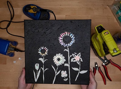
Make animated wall art, powered by pebble-style LEDs, and controlled by a Mini Sparkle Motion. The body is made out of corrugated plastic which is easy to work with by hand. This will be mounted behind an artist's canvas, providing excellent LED diffusion and a subtle texture.
Parts
Mini Sparkle Motion - WLED-friendly ESP32 NeoPixel LED Driver
Adafruit NeoPixel Pebble / Seed LED Strand - 200 LEDs - 2" Pitch
The power supply below provides an all-in-one solution.
-OR-
You can also use an old mobile phone power supply to the wall and an appropriate cable. If the wall power is USB A, the following cable may work well (be careful of length depending on where you mount your art).
Additionally, you'll need a stretched artists canvas, some corrugated plastic (for example Coroplast), duct tape, four small screws, and a USB C power supply. Some optional black cardstock will help make your art more defined if you have white corrugated plastic.
Optional
Tools & Materials
You'll need:
craft knife
soldering iron
screwdriver
Duct tape
Artist's canvas
Small wood screws x4
Electronics
To make the butterfly wing pattern symmetrical, the LEDs are placed in identical, but mirrored, layouts. You can get display the same pattern in both halves by connecting the two strands to the same data line. In order to connect both halves of the Pebble stands to the power and data pins, you first need to combine their wires.
The power of one strip should be connected to the power of the other. The two grounds should also be connected, as should the two data-in lines.
This image shows how you'll connect them:
Finding which wires are which can be tricky. For the LED Pebbles, there are no very obvious markings. Erin St. Blaine has written a guide page which helps identify which wires are which.
Sparkle Motion Skirt with 2D Mapping
By Erin St Blaine
As shown in the Fritzing diagram above, you'll want to trim some wire back on each input side of the Pebble LED line and twist the same lines together such that you now have each like wire connected on the input sides of each strand. These three wires are then connected to the respective pads on the Mini Sparkle Motion: 5V, G/Ground and the Pebble Data in to pin 32.
You can solder straight onto the Mini Sparkle Motion or add a screw terminal block connector (not included, sold separately) to the Mini Sparkle Motion and screw in the wires to make it easy to attach or detach the controller.
There are troubleshooting steps on Erin's page if later in the build the lights are not acting as intended.
The build above shows three colored wires connected to each Pebble LED strand end and then leading to the Mini Sparkle Motion, without a terminal block.
Build
The physical build is made up of two parts:
a mask that slots into the back of your canvas
a box that holds the LEDs
The box is cut from one sheet of corrugated plastic. It will fold up and slot into the back of the canvas and secured with four screws.
Cut the Mask
A butterfly shape will be used to mask out some of the light from the LEDs, leaving just an image of a butterfly -- a little like a reverse silhouette.
First, you need an image of a butterfly. Below is one that you can download, or you can search for your own. You'll need to scale this to the appropriate size for your canvas and print it out on a sheet of paper.
Cut a sheet of your corrugated plastic to fit inside the back of the canvas. This should be very snug, and if anything, slightly oversized.
Once you have this cut out, tape the butterfly shape in the middle, and use a craft knife to cut out the shape. It is easiest to do several light passes with a craft knife rather than a single hard pass.
If your corrugated plastic is translucent, you might want to cut the same shape out of dark paper or card to block more of the light. Here you can see that I've used a bit of tape to hold the dark paper and corrugated plastic together.
Be careful when using a craft knife to avoid cuts. Suitable eye protection would be prudent also.
Build the box
You can 'score' the corrugated plastic using a light pass of a craft knife -- this makes it bend easily in exactly the place you want. It takes a bit of practice to get this right, and the bits you cut out from the butterfly are ideal for cutting practice.
The cuts you need to make for the box are shown in the image below.
Red lines are scores on the front
Blue lines are scores on the back
Black lines are through cuts
Exact dimensions aren't given as it's based off the actual size of the canvas, which will vary a bit from manufacturer to manufacturer. This will be detailed shortly.
The length of the two side folds isn't critical. These are used for screwing the plastic sheet to the canvas.
Start by scoring the inner rectangle. This is the same size as the mask, so you can use it as a template. The outer square should be about 1.25 inches (3cm) bigger, so make sure there's space for this.
Tape the mask to the middle of a section of corrugated plastic making sure that there is sufficient space on all sides. Once you've scored this, you can work outwards by measuring and cutting.
The two blue scores on the side should be approximately half the length of the side, leaving about a quarter at the top and bottom. The blue scores need to sit on the wood of the canvas, so they need to be the same distance in as the wood is thick.
Attach the LEDs
Corrugated plastic is, in some ways, easy to work with, but it does have one problem: not much sticks to it. CA glue holds a bit, and there are some specialized adhesives. However, I've had the most success with duct tape.
Your two strings of LEDs should be positioned in an exact mirror image of each other. This way whatever pattern you display will be mirrored perfectly on each wing. Zig zag the strands up the sheet in the way shown in the photo. Ideally, you want the LEDs on one layer to fall between the LEDs on the layer below. This will prevent any dark spots.
Bringing Everything Together
The control board can be held in place by a bit of tape that's stuck back on itself.
Your USB cable for powering the project needs to run from the wall USB power source and pass through the plastic sheet to the Mini Sparkle Motion board. Cut a cross in at the appropriate place for passing the cable (don't forget to account for the fact that part of the plastic will be covered by the wood of the canvas).
You'll need a way of hanging your art on the wall. I used picture wire, but you could use string or even regular hookup wire. You'll need to make two small cuts on either side of the picture that you can thread the wire through and twist it to keep it secure.
Fold the sheet in to make a box. This should fit snugly inside the canvas.
With the box now inside the canvas, it just needs some screws to hold it in place.
Your butterfly is now ready for software and then to hang on the wall, plug in, and enjoy.
Next, we'll take a look at the software. WLED is a software package that you'll load onto the Mini Sparkle Motion and then configure via your computer.
WLED Setup
The following pages will walk you through installing WLED, setting up the various features within the software and getting your lights turned on and responding to sound or IR control. We'll also show you how to connect sensors via the onboard Stemma port and add button control. And we'll show you how to set up multiple strands and multiple controllers and sync them together for larger scale projects.
Ready? Set? Let's go.
WLED Software
Board Choices
WLED runs on several different boards in Adafruit's collection. There are different benefits to each, but the installation process is largely the same. This page contains instructions for multiple boards -- be sure to use the pinouts and installation instructions for the one you're using,
Sparkle Motion
This is our flagship ESP32 board, designed with WLED and Xlights in mind. It has 4 outputs and is set up to drive either 5v, 12v or 24v pixels. It's a workhorse of a board and for larger projects it's the clear winner. It has an onboard microphone for instant sound-reactive support, and an IR sensor built in, to make it easy to control your project with an infrared remote. It also has a couple stemma ports so you can add your own sensors or peripherals.
Sparkle Motion Mini
The Sparkle Motion Mini is a smaller version of the Sparkle Motion board. It has two LED outputs, a microphone, and two stemma ports that make it easy to add an IR sensor or other peripherals. It's got an onboard NeoPixel and a small footprint, making it perfect for wearables or smaller projects. It will power a whole lot of pixels through the onboard USB port: it's safe to draw up to 4A through this port, giving you plenty of power for most wearable projects.
At this time, the Sparkle Motion Mini works best with WLED 0.15.1 -- the extra GPIO for the microphone pins are not supported in WLED 0.15.0. This should be fixed with the release of version 16.
To get mic support now, the following combined .bin file can be used. Get it by downloading this zip file:
esp32_bootloader_v4_WLED_0.16.0-alpha_ESP32.zip
To install, extract the .bin file from the zip and then follow the same ESB Web Flasher process used for installing CircuitPython. At the "Programming the Board" step, choose the .bin file and leave offset as 0x0.
QT Py Pico ESP32
The QT Py Pico is small and affordable, so usually my go-to for smaller costumes or wearables. It also has a range of BFF add-on boards that add functionality. Here's a guide with more QT Py info. The QT Py will drive up to around 30 pixels through the onboard USB port, so if you have more LEDs than that you may want to consider the Sparkle Motion Mini instead, or you can power the board through the +5v pin.
Note: WLED works on the QT Py Pico but NOT on the S2 or S3 versions, at the time of writing.
Feather Huzzah ESP32
The Feather Huzzah ESP32 the top of the line. It's a great choice for projects where you want to add sensors, interaction, or drive a whole lot of LEDs. It's the most reliable as well -- I've run these for two months straight with no power cycling and they just keep on truckin. Adafruit has a very wide selection of Feather Wing boards that connect to the Feather microcontroller line. The sky is the limit with these boards.
It also comes in a version with a high-powered WiFi range extender! If you're trying to sync multiple instances across distance, check this one out. Feather Huzzah ESP32 V2 w.FL Antenna.
Feather Huzzah ESP8266
The Feather Huzzah ESP8266 will run WLED as well but won't drive as many pixels: the ESP32 limit on WLED is around 1000 pixels per input, but the ESP8266 tops out at around 500. It's about $5 cheaper though, so for smaller projects it's a great way to save a little money and still have access to all the FeatherWing options in the Adafruit store.
Driver Update
Some versions of our controllers have a new serial chip which needs a driver installed before we can install WLED. Head over to our How to Install Drivers for WCH USB to Serial Chips tutorial and download and install the new driver.
If you have an older QT Py with CP2102 USB-to-Serial bridge, use SiLabs’ driver instead.
Install WLED
These next steps require a Web Serial-compatible browser. As of this writing, that means Google Chrome, Microsoft Edge, or Opera “desktop” browsers. Other browsers (Safari, Firefox, Explorer, and anything mobile) won’t work.
Visit https://install.wled.me/
Plug your microcontroller into your computer with a known good USB cable. Click "Install" and select the port for your board.
Depending on the USB-to-serial bridge chip on the board, you might see one or two serial ports. On Mac, for instance, there might be both “/dev/cu.usbmodem[number]” and “/dev/cu.wchusbserial[number]”. Use the “wchusbserial” one.
After successful installation, enter your WiFi network name and password when prompted. This must be a 2.4 GHz WiFi network; ESP32 does not support 5 GHz networks. If it can’t connect, then as a fallback WLED will create its own 2.4 GHz WiFi access point.
If you don't see the "Connect to Wi-Fi" prompt, you'll need to set up your WiFi network using AP (access point) mode. Open up your WiFi settings and look for a WiFi network called WLED-AP. Connect to this network using the default password wled1234. The WLED interface will pop up in its own browser.
From here, go into Config/Wifi Settings and enter your WiFi credentials near the top. Give your project a name in the mDNS field a little further down the page. Now you can type in "projectname.local" (where "projectname" is your mDNS name) into any web browser on the same wifi network to access your microcontroller.
You can also scan the QR code below to open access point mode.
For more help and troubleshooting tips visit the Getting Started page on the WLED knowledge base.
Setup & Preferences
WiFi Setup
Head to the WiFi Setup screen under Config and create a good URL so you can control your project from any web-enabled device. Call it something you'll remember, that's easy to type into any web browser on your WiFi network in order to connect to your project.
In Safari or Chrome on your phone or computer, type in this web address to access the WLED interface: http://projectname.local (where "projectname" is whatever you put into this field).
Check out the Additional Settings page for more info on accessing your project. WLED has an "access point mode" that doesn't require a WiFi network for when you're out on the go. It's also helpful to download one of the WLED apps to help manage and organize your projects.
LED Preferences
Next, head to the LED Preferences tab under the Config menu.
Scroll down to Hardware Setup. Put your total number of LEDs into the "Length" field and change GPIO to the pin number associated with the pin you soldered to. Check the pinout diagram for the board you're using (it's the number in yellow).
Use It
Now you can use any computer or handheld device to control your LEDs.
Make sure your device is on the same WiFi network as your board. Navigate to your custom URL (projectname.local/ ) in a web browser. You'll see a color picker above a whole bunch of color palette choices.
Choose a color, choose an effect, and watch your lights animate and glow!
Save your favorite combinations as presets, create playlists, control the speed and intensity of the animations, and lots more. This web app is incredibly intuitive and easy to use.
Head over to the WLED wiki at https://kno.wled.ge/ to delve into all the particulars.
WLED Config
Next, we'll tell WLED about our physical setup. We'll give our project a name and easy-to-remember URL and tell the software how many LEDs we have set up on each pin.
WiFi Setup
Head to the WiFi Setup screen under Config. This is where your network credentials live, so you can change them if needed. Scroll down to the mDNS field and create a good URL so you can control your project from any web-enabled device. Call it something you'll remember, that's easy to type into any web browser on your WiFi network in order to connect to your project.
In this example, I'd go to my web browser on my phone, iPad, or computer, and type in "http://projectname.local" to open up the WLED interface on my screen. Your device must be on the same WiFi network as your board.
LED Preferences
Next, head to the LED Preferences tab under the Config menu.
Scroll down to Hardware Setup. The Sparkle Motion Mini board has 2 outputs to attach LED strips: GPIO pins 32 and 33.
WLED allows up to 3 strips to be connected at once. The strips can be of different types, lengths, and color order. Select your LED type, length, and GPIO pin. If you have multiple strips connected, click the + button and enter the additional strips in the same way.
Click "save" and if you've done everything correctly, your light strands should come on in a warm, cheerful yellow color. Success! Time to start making pretty light animations.
Troubleshooting
If your lights didn't come on, here are a few things to try:
Head back to WLED and check your pinout configuration under LED Preferences. Be sure the pin number is the correct GPIO for the attachment point you used.
Check your wiring! Be sure you connected to the IN end of the LED strip. These strips can be inconsistent, so this is a pretty common problem. Use an alligator clip to try connecting the data wire on the other end (the power and ground wires should work from either end).
Try re-uploading the WLED software.
If the lights come on but you can't control them: i.e. you type in "projectname.local" into your browser and it won't connect, make sure you're on the correct WiFi network. If you're on a different network than the one you set up the sofware on, you won't see the WLED connection.
If your lights came on in blue or green instead of yellow, your color order is wrong. See below to fix.
If only half your lights came on, be sure you've got the correct number in the "length" field under LED preferences.
If your lights came on in a variety of weird colors and looking like a 1950s diner interior, you may have the wrong LED strip type selected. RGBW strips and RGB strips are not the same, so be sure you've got the correct strip type, or you'll get very odd behavior.
If your microcontroller hangs or keeps rebooting, or gets really hot, you may have the power and ground lines switched. Unplug right away and check: this is a fast way to brick your controller.
Color Order
If your lights have come on in any color other than a warm yellow, there's one more setting to change. LED strips and pixels are not all standardized, and sometimes the red, green, and blue LEDs inside are connected in a different order.
In the main interface window, choose "solid" as your effect and red as your color from the color picker.
If your lights come on in any color other than red, your color order is set incorrectly. This is an easy fix. Head back to the LED settings tab and find the Hardware Setup section (this is where you set up your pin number earlier). Choose BRG from the dropdown, click save, and see if your pixel colors match your color picker now. If not, try another combo until the lights look correct.
Setting the Light Pattern
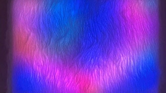
Now that the electronics and software are set up, it's time to create the WLED pattern to light up the butterfly. There aren't any hard-and-fast rules here, and you can illuminate your butterfly however you like.
Personally, I like a blue butterfly with a shimmer of purple to give the effect of iridescence. This is inspired by butterflies such as the Common Blue and Holly Blue. Another common color pallet in nature is orange and red. However, you don't have to be limited by real life butterflies, you can pick whatever you like.
To create the effect for a Common Blue inspired butterfly, first you have to make some settings in the Colors tab in WLED. Pick a blue for color 1 and purple for color 2, then select Colors 1&2 in the pallet type list.
You can now switch to the effects tab and select your effect. I like the Blends effect.
Finally, in order to make your butterfly start with the same pattern when it's powered on, you need to save the setup as a preset.
In the Presets tab, click Create Preset, give it a name, and click Save Preset. This will give it a preset ID. Remember this as you'll need it in the next step.
Go to Config > LED Preferences and scroll down. Near the bottom you'll find the Defaults section, and in this section, you'll see the option to Apply Preset x At Boot. Change the number to the ID of the preset you just created and scroll back to the top to save the settings. Now, each time you power on your device, it'll start with the correct lighting.