Use Advances in 3D Time-of-Flight Sensors to Measure Peak Height and Fill Level During Production
There’s a common belief that progress in technology is a linear and clear process, and the semiconductor industry promotes this mindset by publishing “road maps” of process technology and node shrinkage looking five and ten years out, making it all sound like a very predictable extrapolation of past developments.
Of course, the reality of progress is very different in many cases. Anyone looking at vacuum-tube technology in 1947 and predicting its near and medium-term future would not have included totally disruptive events such as the transistor. Forecasters looking at transistors and circuits in the early 1950s would not have considered the integrated circuit, which appeared at the end of that decade.
Technological advances are not just the result of such disruptive, revolutionary, and often unforeseen events. Instead, they are due in many cases to practitioners in one area seeing, leveraging, and making use of developments in other, unrelated disciplines. For example, what made many of the advances in solid-state process technology possible was the availability of highly refined, purified basic elements and compounds and optical advances for space telescopes.
We’re seeing another example of this leveraging of cross-disciplinary advances, or 1+1 > 2, with respect to time-of-flight (ToF) systems and sensors, which have become increasingly necessary for advanced machine learning (ML) and computer vision (CV) systems.
ToF systems have grown in adoption over the last decade. Although their fundamental principles have been known for a long time, practical implementations have been difficult and impractical. Now, thanks to fast and powerful computational systems and advances in basic optical products, such as photosensors and controllable lasers, ToF is going mainstream.
What is ToF?
All ToF sensors measure distances using the time it takes for an optical signal (photons) to travel between two points, from the sensor’s emitter to a target and then back to the sensor’s receiver. This is like the principles of radar, where RF energy transmission and returned reflections are used. ToF technology and practicality are being accelerated by their use in the quest for autonomous self-driving vehicles and intelligent, vision-enabled robotics.
There are two forms of ToF: direct and indirect (Figure 1). Direct ToF sensors send out short pulses of light that last just a few nanoseconds and then measure the time it takes for some of the emitted light to return. In contrast, indirect ToF sensors send out continuous, modulated light and measure the phase of the reflected light to calculate the distance to an object. The choice of which you use depends on the application.
 Figure 1 : The direct ToF sensor uses short pulses of light and precise time measurements (left); the indirect approach uses a continuously modulated output and relative phase measurements (right). (Image source: Terabee/Switzerland)
Conventional non-ToF cameras map only two-dimensional, color-oriented images of individual pixels plotted in a grid. Highly accurate ToF sensors, however, add the third dimension to traditional photographs at pixel ratios of nearly 1:1.
They do this by creating a “point cloud” to visually represent a single pixel in the X, Y, and Z coordinates of the camera's field of view. ToF sensors can even add a third dimension to videos, which are, in their most basic sense, a collection of images. In doing so, they create a dynamic, three-dimensional point cloud and a real-time, depth-mapped video stream.
Not limited to vehicles
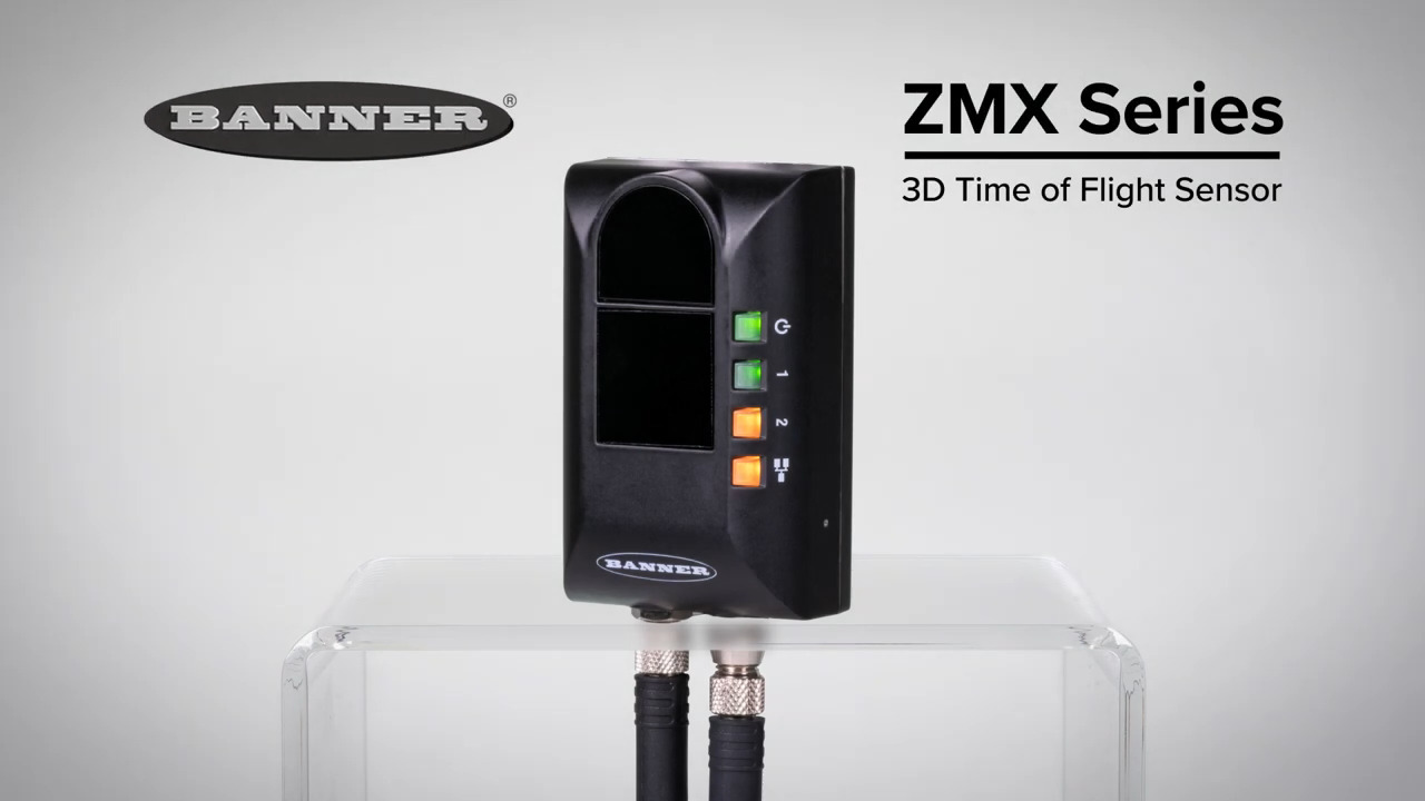
The usefulness of ToF goes beyond autonomous vehicles, as illustrated by the ZMX Series 3D ToF sensors from Banner Engineering (Figure 2). The ZMX-3DE2500HF unit, with its 850 nanometer (nm) infrared (IR) light source, can measure and monitor objects within a 3D area and provide a single-sensor solution for filling applications on production lines. It can detect both the peak height and average fill level.
 Figure 2: The ZMX Series 3D ToF sensor can measure, monitor, and detect peak height and average fill level on production lines. (Image source: Banner Engineering)
The ZMX Series features a large 60° × 45° field of view (FOV) with a resolution of 272 × 208 pixels, along with a distance range of 200 to 2,500 millimeters (mm). Because the sensor can detect items of any size, shape, or orientation, it is an ideal tool for automated industrial and production applications in which materials, products, or packages accumulate within a defined area. Another interesting feature is that it is entirely self-contained and does not require a separate controller or PC. There are only a few settings to define, and it can be deployed in minutes. The physical connection is also simple; it requires one power cable and one Ethernet cable.
The ZMX Series sensor can be used to:
- Monitor the contents of containers that are collecting items from a chute or conveyor in an automated system. By combining digital imaging and thousands of laser measurement points, it can detect objects within a three-dimensional area.
- Recognize the maximum height of objects regardless of where the highest point might be within that sensing area. It is also helpful in calculating fill volume. A single 3D sensor is an excellent way to ensure containers are filled consistently, prevent overfill, track fill rates, and fine-tune processing speeds.
- Simplify applications that otherwise would require multiple single-point sensors. A single 3D sensor is easier to install and track and delivers a more reliable performance. Traditional single-point technologies may be unreliable when measuring an accumulation of shapes.
For example, when a bin is put in place to collect a quantity of small rectangular boxes, the contents accumulate and form a pile with an unpredictable shape. To accurately determine when the bin is full, a sensor solution must be able to detect fill height variations across the bin’s total area.
For example, a single laser may indicate a low by perceiving a gap between two objects, or an ultrasonic sensor may not have a reading at all due to the signal being reflected away by an oddly angled or shaped object (Figure 3). By contrast, one centrally positioned ZMX sensor provides complete area coverage across all three dimensions.
; in contrast, a ToF system provides complete 3D area coverage (right)") Figure 3: An ultrasonic sensor may be misled by gaps at the target or odd reflections (left); in contrast, a ToF system provides complete 3D area coverage (right). (Image source: Banner Engineering)
Figure 3: An ultrasonic sensor may be misled by gaps at the target or odd reflections (left); in contrast, a ToF system provides complete 3D area coverage (right). (Image source: Banner Engineering)
Then there’s setup simplicity
The physical interconnections are straightforward since these units have only two connectors plus some useful indicator LEDs. One is a female M8 connector for Ethernet, and the other is a male M8 circular connector carrying DC power (12 volts DC (VDC) to 30 VDC) and providing two digital I/O channels (Figure 4).
 Figure 4 : The ZMX Series sensor unit provides user-friendly indicator LEDs and has simple wiring interconnection via two M8 circular connectors. (Image source: Banner Engineering)
While the electrical connections are simple enough, one of the challenges with position and area sensors is setting them up so that they see what they need to see: no more and no less.
Fortunately, the ZMX Series makes this setup relatively easy. The Banner 3D Configuration software displays the information you need to set and fine-tune sensor parameters and all connectivity and I/O settings (Figure 5).
 Figure 5 : Setup and configuration of the ZMX Series is simplified by the powerful and visual Banner 3D Configuration software package. (Image source: Banner Engineering)
This software divides the workspace into several panes:
1. The Image Pane Parameters include zoom; x, y, z coordinates; image color; and view selection.
2. The Image pane displays the current image captured by the sensor. It also allows the presentation of a previously saved file for viewing while disconnected from the sensor, the saving of an image file, and manual triggering of the sensor when Trigger mode is set to External or Software.
3. The Connection pane enables a connection to a sensor.
4. The Sensor Controls pane controls the trigger mode and illumination output.
5. The Fill Level pane includes options for the region of interest and sensor controls, as well as live fill and peak-height data.
6. The Communications pane sets the sensor's communication protocol and DHCP option.
7. The Sensor Maintenance pane includes sensor information and options to update the firmware, restore default or previous settings, and back up the current sensor settings.
Conclusion
It’s often difficult to consistently and accurately sense, measure, and monitor objects within a three-dimensional area to detect peak height and average fill levels in real-world production settings. The ZMX Series 3D ToF sensor from Banner Engineering uses the latest innovations in optical-based ToF hardware technology and software algorithms to address the issues and make it much easier to provide consistent, reliable results. It’s supported by a graphical configuration tool that dramatically simplifies set-up, installation, and actual use.
Related Content
1: ZMX Series 3D Time of Flight Sensor
https://www.bannerengineering.com/us/en/company/new-products/zmx-series.html#/
2: ZMX Series 3D Time of Flight Sensor Quick Start Guide
https://info.bannerengineering.com/cs/groups/public/documents/literature/229164.pdf
3: ZMX Series 3D Time of Flight Sensor Instruction Manual
https://info.bannerengineering.com/cs/groups/public/documents/literature/230551.pdf
4: Eliminate Conveyor Jam False Alarms to Boost Factory Automation Productivity
About this author

Bill Schweber is an electronics engineer who has written three textbooks on electronic communications systems, as well as hundreds of technical articles, opinion columns, and product features. In past roles, he worked as a technical web-site manager for multiple topic-specific sites for EE Times, as well as both the Executive Editor and Analog Editor at EDN.
At Analog Devices, Inc. (a leading vendor of analog and mixed-signal ICs), Bill was in marketing communications (public relations); as a result, he has been on both sides of the technical PR function, presenting company products, stories, and messages to the media and also as the recipient of these.
Prior to the MarCom role at Analog, Bill was associate editor of their respected technical journal, and also worked in their product marketing and applications engineering groups. Before those roles, Bill was at Instron Corp., doing hands-on analog- and power-circuit design and systems integration for materials-testing machine controls.
He has an MSEE (Univ. of Mass) and BSEE (Columbia Univ.), is a Registered Professional Engineer, and holds an Advanced Class amateur radio license. Bill has also planned, written, and presented on-line courses on a variety of engineering topics, including MOSFET basics, ADC selection, and driving LEDs.

Have questions or comments? Continue the conversation on TechForum, DigiKey's online community and technical resource.
Visit TechForumMore Blogs from this Author