Eliminate Conveyor Jam False Alarms to Boost Factory Automation Productivity
Contributed By DigiKey's North American Editors
2023-08-25
Fast-moving conveyors are widely used in factory automation to accelerate production and enhance efficiency. But occasionally, things can go wrong. A frequent problem is jamming; one item gets stuck, and then others quickly pile up behind. This is not only bad for throughput and damaging to the conveyor system, but it can also be dangerous for nearby workers.
A laser detector is one solution for eliminating these jams. By shining a beam across the conveyor and detecting the reflection, the sensor can check for lodged items and stop the system before damage occurs. While simple to install and use, laser detectors are not foolproof. For example, if several items are moving, but there’s no gap between them, the system could conclude there’s a jam and unnecessarily stop the conveyor.
Recent laser sensor product introductions reduce the number of false alarms by leveraging more advanced optical technology and software algorithms.
This article briefly describes the two types of light sensors used for jam detection: LED and lasers. It then focuses on the time-of-flight (ToF) laser and considers the key factors that determine how well the sensor performs. The article also introduces a real-world ToF laser sensor from Banner Engineering and illustrates how to set one up for a conveyor jam detection application.
What is a laser sensor?
A laser sensor uses a coherent light beam to detect an object and help determine its distance. In the absence of an object, light is reflected from a fixed reference surface. However, if an object does cross the beam, light reflects with a different intensity and from a shorter distance, thereby triggering the sensor. An LED sensor can also detect the presence of objects using light and tends to be less expensive, but the cost gap has closed in recent years, and the laser sensor is technically superior in several ways.
For example, compared to LED sensors, the laser type offers a significantly greater sensing range and higher detection precision. Moreover, the tightly-controlled laser beam produces a small spot over a long range with good reflection, even from poor reflective surfaces. Such attributes enable laser sensors to, for example, detect tiny objects, even down to thin threads. A further advantage is that a laser sensor can detect objects through holes or narrow openings (Figure 1).
 Figure 1: Laser sensors offer good reflection even from products with poor reflective surfaces. (Image source: Banner Engineering)
Laser sensors use two techniques to determine the distance to the detected object: triangulation or beam ToF. The triangulation technique uses the angle of the reflected light to determine its distance from the sensor. ToF sensors, as the name suggests, measure the time taken for the beam to travel to the object and back. They then use the known speed of light (“c”) to calculate the distance to the object using the simple formula: distance to the object in meters (m) = ToF in seconds (s)/2 x c in meters per second (m/s) (Figure 2).
 Figure 2: The ToF technique measures the time taken for a light pulse to travel to the object and back, and then applies a simple formula to calculate the distance to the object. (Image source: Banner Engineering)
Laser sensors using triangulation are less expensive and more precise over short distances up to 100 mm. The ToF types are better for long distance detection up to 24 m. Conveyor jam detection applications require the laser sensor to operate over several meters, so for the rest of this article, only the latter type will be considered.
Selection criteria for laser sensors
While laser sensors are technically superior to LED devices, careful selection is required to ensure the best sensor is selected for a particular application.
Key parameters to consider include:
- Repeatability (or reproducibility): This refers to how reliably the sensor can repeat the same measurement in the same conditions. For example, repeatability of 0.5 mm means that multiple measurements of the same target will all be within ±0.5 mm.
- Minimum object separation (MOS): This refers to the minimum distance a target must be separated from its background to be reliably detected by the sensor. A MOS of 0.5 mm means that the sensor can detect an object that is at least 0.5 mm away from the background (Figure 3).
- Resolution: This is a measure of the smallest change in distance a sensor can detect. A resolution of 0.5 mm means that the sensor can detect changes down to 0.5 mm. This spec is the same as best-case repeatability, but it is expressed as an absolute number instead of a tolerance.
- Accuracy: This is the difference between actual and measured values. It is used to assess measurement precision of an unknown distance without a reference target. This measurement is useful when comparing measurements from multiple sensors.
- Linearity: This is an alternative parameter to accuracy when looking at relative changes in measurements from a known reference target. It is similar to calibrating the 4 and 20 milliamp (mA) points for an analog sensor, where all distance measurements are then relative to the taught conditions.
 Figure 3: MOS is the minimum distance a target must be separated from its background to be reliably detected by the sensor. (Image source: Banner Engineering)
Selecting a laser sensor starts with matching its capability to the dimensional characteristics of the application. For example, whether objects to be detected are centimeters away or several meters distant. But there are further selection criteria depending on the color and reflectivity of the objects to be detected.
Optimizing the laser sensor for challenging targets
Common challenges for laser sensors include objects with highly reflective surfaces and those with dark or matte surfaces. To cope with the former, the engineer should choose a laser sensor with automatic gain compensation such that the device decreases its gain to lower laser intensity, and hence the magnitude of the reflected light. Gain compensation helps to maintain accuracy. When looking for dark or poorly reflective objects, the return signal can be very weak and difficult to detect. A solution is to specify a laser sensor that automatically increases its gain to amplify the reflected signal to reliably detect targets that other sensors might struggle to observe.
For many applications, a tightly focused beam spot is ideal. For example, a small spot works best in situations where the target comprises several colors. A focused spot can be targeted at just one color on a multicolored product for a consistent and reliable reflection (Figure 4, top). A small beam spot is also useful for focusing on a particular point of a profiled surface. Such focus again ensures robust operation (Figure 4, bottom).
 Figure 4: A tightly focused spot works reliably on multicolored and profiled surfaces. (Image source: Banner Engineering)
But selecting a laser sensor with a focused spot is not the answer for all applications. There are times when a larger, more diffused spot is a better option. For example, a large spot illuminating a rough surface enables averaging of the reflected light for greater measurement stability (Figure 5).
 Figure 5: A more diffused spot works better on rough surfaces as it tends to average out reflections from high and low areas. (Image source: Banner Engineering)
Clearing conveyor jams
Fast-moving factory conveyors can be prone to jamming, particularly at curves, where goods can pile up rapidly at the bend exit. A curve is also prone to false jams as the bulk flow of packages often offers few gaps for conventional sensors to detect a jam (Figure 6).
 Figure 6: Conveyor curves are prone to false jam alarms as the bulk flow of packages offers few gaps for conventional sensors to detect a lack of movement. (Image source: Banner Engineering)
Common workarounds for false jams often cause more problems than they solve. Typical methods include adding delay timers to give false jams time to “clear.” While such delays can work, in the event of a more serious jam, the response is delayed and can cause excessive wear on equipment as more packages pile up and stress conveyor components. Moreover, the forces involved in a jam can damage the goods stuck on the conveyor. Finally, serious jams are often addressed by workers who attempt to clear the line during the delay period with so-called jam poles. This poses a risk as workers are accessing hazardous areas while large electric motors are still running.
False jams are common: Banner Engineering cites a customer that discovered 82% of conveyor jams “detected” using conventional sensing methods were false alarms. False alarms not only cause damage and endanger staff, but they also cost money. These costs include:
- Lost productivity
- Downstream processes starved of work
- Lost time spent by maintenance staff diagnosing false problems
- Wear and tear on conveyor systems through constant stopping and starting
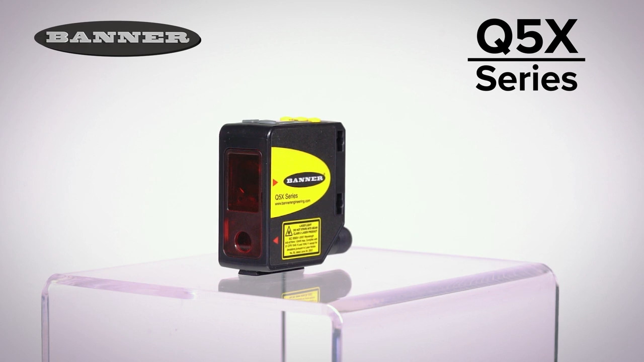
The solution to this engineering challenge is a laser sensor that minimizes false jam detection, yet reacts quickly to real blockages. One option is the Q5XKLAF10000-Q8 from Banner Engineering’s Q5X line of ToF sensors (Figure 7). This sensor operates over a range of 50 mm to 10 m, has a repeatability of ±0.5 to 10 mm, a MOS of 1 to 70 mm, a resolution of 1 to 30 mm, a linearity of ±5 to 150 mm, and an accuracy of ±3 to 150 mm. This laser sensor also has automatic gain compensation and a user-selectable response time of 3, 5, 15, 25, or 50 milliseconds (ms).
Other key features of the Q5XKLAF10000-Q8 that make it particularly suitable for conveyor applications include:
- A built-in jam detection algorithm that does not rely on gaps to sense package flow
- The ability to detect various package types, including boxes, bottles, and polybags
- An industry standard M12 connector
- A variety of mounting brackets
 Figure 7: The Q5XKLAF10000-Q8 laser sensor is a compact conveyor jam detector that includes a built-in jam detection algorithm that does not rely on gaps to sense target object flow. (Image source: Banner Engineering)
Setting up a laser optical sensor
For the conveyor curve application outlined above, the Q5X laser sensor should be mounted immediately after the curve for the earliest jam detection. The device features two output indicators, a display, and three buttons. It should be mounted on a bracket to ensure the best detection reliability and MOS performance. A suggested orientation is shown in Figure 8. The laser sensor is then wired up, as shown in Figure 9.
 Figure 8: The Q5XKLAF10000-Q8 laser sensor works best when mounted at 90° to the target object flow. (Image source: Banner Engineering)
 Figure 9: Electrical and signal connection for the laser sensor is through a standard M12 connector. This diagram shows the setup for a 0 to 10 volt analog system. (Image source: Banner Engineering)
Once oriented and powered up, the laser sensor must be introduced to its reference surface. This is the part of the conveyor or other fixture that reflects light when no object is passing through the sensor beam. The selection of the optimum reference surface is key to the overall performance of the laser sensor. This surface must feature a matte or diffused surface finish, be free of oil, water, or dust, have a permanent location, and be free of vibration. The surface should also be between 200 mm and the maximum sensing range. Items to be detected should pass as close as possible to the sensor and as far as possible from the reference surface.
The Q5X laser sensor is programmed using the buttons and display. Programming is achieved by accessing menus and entering values for functional parameters. For example, a key parameter is “dual mode”; this mode records the distance and amount of light received from the reference surface. The sensor then records an object passing between the sensor and the reference surface when the perceived distance or amount of returned light changes.
Another important parameter that requires programming is “jam retroreflective.” This is an extension of dual mode that optimizes jam detection when a background is present. An independent jam range value is set, which defines the minimum object movement required to qualify as “not jammed,” which, in combination with an automatically determined intensity threshold, determines that an object is moving. There is a similar “teach” mode for optimizing jam detection when no background is present.
Conclusion
Keeping factory automation conveyors humming is important to maintain productivity and ensure worker safety. But even on the best production lines, jams happen. However, conventional approaches used to detect these jams often trigger false alarms. As shown, the latest generation of laser sensors from companies like Banner Engineering have advanced features that minimize false detection, and are relatively easy to install and program for optimum performance.
Disclaimer: The opinions, beliefs, and viewpoints expressed by the various authors and/or forum participants on this website do not necessarily reflect the opinions, beliefs, and viewpoints of DigiKey or official policies of DigiKey.