How to Use IO-Link to Easily Adapt RTD Connectivity to the Smart Factory
Contributed By DigiKey's North American Editors
2023-09-21
Resistance temperature detectors (RTDs) are widely used as transducers due to their accuracy, wide sensing range, ruggedness, and other desirable attributes. In legacy implementations, a voltage that is proportional to temperature was sensed across a current-driven RTD, transformed into an analog 4 mA to 20 mA current, and sent to the system readout or operator via a wired “transmitter.”
Although this approach is effective, direct, and advantageous, it is not compatible with digital and processor-based architectures. One suggested solution for this issue involved upgrading the transmitter to digitize the RTD signal at the source using an internal analog-to-digital converter (ADC) and transmitting the signal via a suitable input/output (I/O) format and protocol.
However, these upgrades are not sufficient to meet the needs of the smart factory. Today’s industrial systems need much more than a digitized representation of the RTD signal. They require multichannel operation, a high degree of precision in the analog-to-digital conversion, and various forms of fault detection and error checking to ensure the received data is valid.
Today’s industrial systems also need some provision for the remote adjustment of key sensor-interface parameters. Finally, they need an I/O format and interface that is robust, supports advanced setup and data-reporting features, and ensures data integrity.
This article provides an overview of RTDs and how they’ve evolved. It introduces IO-Link as an interface option. It explains how to implement a high-performance RTD-based temperature sensing channel using an advanced analog front end (AFE) and a signal-conditioning IC. A suitable kit is presented to help evaluate an IO-Link transceiver for an RTD implementation.
RTD basics
An RTD translates the physical variable of temperature into an electrical signal and is typically used to measure temperatures between -200 and +850°C, with a highly linear response exhibited across this temperature range. Metal elements commonly used in RTDs include nickel (Ni), copper (Cu), and platinum (Pt), with Pt100 (100 ohms (Ω)) and Pt1000 (1000 Ω) platinum RTDs being the most common.
An RTD interface can consist of two, three, or four wires, with the three and four-wire versions being the most popular. Because they are passive devices, RTDs require an excitation current to produce an output voltage. This is usually generated using a voltage reference, buffered by an operational amplifier (op amp). This drives current into the RTD to produce an output voltage signal across its two terminals that varies in response to changes in temperature.
This signal varies from tens to hundreds of millivolts (mV) depending on the type of RTD used and the measured temperature. It is then conditioned and sent to an analog readout, strip chart recorder, digital display, or processor-based control system.
It began with the all-analog loop
Historically, the basic electronic interface for industrial measurement and control systems has been the 4 to 20 milliamp (mA) current loop. This interface link can be used for both sensors and actuators. For sensors, the signal from the transducer is amplified and conditioned at the source before transforming into a signal ranging from 4 mA, representing the low-end limit of the range, to 20 mA for the high-end limit (Figure 1).
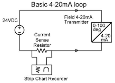 Figure 1: The measurement of temperature in industrial settings has traditionally relied upon a 4 mA to 20 mA current loop between the RTD interface and the readout located some distance away. (Image source: Analog Devices)
The distance between the sensor and the readout can be tens or hundreds of feet, so there are several reasons to use a current loop for the link:
- As a current-sourced signal rather than a voltage-driven source, the loop is unaffected by distance; there is no concern about IR voltage drop, and current cannot be “lost” in the loop wires.
- As a low-impedance link, it is relatively immune to electromagnetic interference (EMI) pickup and signal corruption, even over long distances.
- Finally, the current loop is self-diagnosing: the current drops to zero if the loop breaks (the most common failure mode). This current drop is easily detected.
The electronic unit that does the all-analog signal processing is called a transmitter. Early IC-based transmitters required a separate local power supply for their operation. The power supply was used to excite the sensor (if needed) and power the conditioning circuitry. Later, lower power transmitter ICs added functionality and features, and added one very important capability: they were “loop powered” and could draw their operating current from the “unused” 4 mA of the loop current, thereby eliminating the need for a local power supply.
For example, Analog Devices’ AD693 is a loop-powered 4 mA to 20 mA sensor transmitter that was introduced in the 1980s (Figure 2). It is still available in its original ceramic dual inline package (DIP) as well as newer surface-mount packaging, a testament to the longevity of this industrial-focused IC.
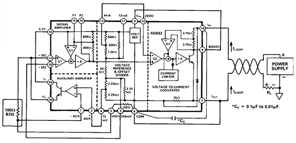 Figure 2: The all-analog, loop-powered AD693 RTD transmitter eliminates the need for a power supply at the RTD interface end of the current loop. (Image source: Analog Devices)
Going digital
As digital control became standard, it was necessary to digitize the analog current-loop signal. To accomplish this today, an AFE is needed to amplify and condition the low-amplitude RTD signal so the ADC can digitize it. The digitized signal is then sent to the process controller, such as a microcontroller unit (MCU), via a communications interface (Figure 3).
 Figure 3: The shift to digital control necessitated an AFE with an MCU compatible output. (Image source: Analog Devices)
Due to the conflicting technical and IC process demands of the sensitive AFE versus the digital I/O, implementing the critical AFE and associated digital interface circuitry is challenging and requires multiple ICs. Fortunately, advances in IC technology have made a highly-integrated, single-chip RTD interface possible. In addition, these integrated ICs incorporate many other functions and features needed for a more sophisticated and error-free system.
An example of a single-chip integrated solution is the AD7124-4, a complete RTD AFE in a single package (Figure 4). This four-channel, low-noise, and low-power 24-bit IC includes a programmable gain amplifier (PGA) and voltage reference. It also provides the excitation current for the RTD, eliminating the need for a separate precision current-source.
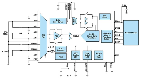 Figure 4: The AD7124-4 is a complete multi-channel RTD interface including current source, signal conditioning, and digitization. (Image source: Analog Devices)
In addition to the core functionality embedded within the AD7124-4, the device also provides multiple types and levels of self-diagnostic and error-detection functions that help it achieve Safety Integrity Level (SIL) certification. This certification is critical in high-reliability and mission-critical applications.
The digital interface between the AD7124-4 and its associated MCU is a three or four-wire serial interface that is SPI, QSPI, MICROWIRE, and DSP compatible. That said, such interfaces are not suitable for direct connection or use with long-length signal paths. Instead, this long link needs to be formed via an interface/format translator or adapter that implements the selected network protocols to connect to the process controller. This interface will likely use an industrial network such as PROFINET or industrial Ethernet.
However, using these specialty interfaces has several disadvantages. For example, adding a network-specific circuit in the sensor design significantly increases cost, especially if the industrial networks are proprietary. It also limits the market for a sensor to customers already using that network. For the same sensor to work with different network protocols, a redesign is necessary.
Another frustrating complication is that the number and type of diagnostic features vary significantly among network types. Depending on the choice of interface format and protocol, it can be difficult for factory operators to identify and maintain sensors and resolve any performance issues that arise once they have been installed in the field.
IO-Link addresses the connectivity challenges
Designers of smart factories require intelligent, flexible, and easy-to-deploy sensors and actuators to facilitate better decision-making toward more readily optimized manufacturing processes. One viable approach is to design a sensor independent of the various industrial networks, thereby reducing development costs and broadening the potential customer base. IO-Link technology enables this approach by allowing traditional sensors to become intelligent.
By using IO-Link master and device transceivers, industrial system designers have a powerful and flexible way to move intelligence from the programmable logic controller (PLC) or other system controller, closer to the sensors on the factory floor (Figure 5).
 Figure 5: With IO-Link master and device transceivers between a sensor’s MCU and a process controller, the industrial data system becomes more powerful and flexible. (Image source: Analog Devices)
IO-Link is a three-wire, point-to-point communication interface with standardized connectors, cables, and protocols that links sensors (and actuators) with industrial control networks. In IO-Link applications, a transceiver acts as the physical layer (PHY) interface to an MCU or other controller running the data-link layer protocol. IO-Link is designed to work within the industry standard three-wire sensor and actuator infrastructure, comprising an IO-Link master and IO-Link device components (Figure 6).
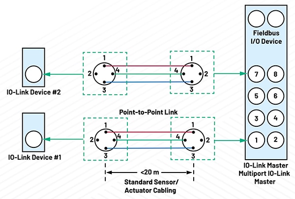 Figure 6: The IO-Link physical interconnection has an IO-Link master and supports multiple IO-Link device components. (Image source: Analog Devices)
The advantage of using IO-Link is that it carries four different types of transmission data: process, diagnostics, configuration, and events. This allows sensors to be quickly identified, traced, and attended to if a malfunction occurs. IO-Link also enables remote configuration. For example, if the temperature threshold for a process alarm to be triggered requires changing, it can be done remotely without needing a technician to step onto the factory floor.
The point-to-point connection between the IO-Link master (multiport controller or gateway) and the IO-Link device (sensor or actuator) uses standard connectors common to industrial systems (M8 and M12 connectors are the most widely used), and an unshielded cable that can be up to 20 meters (m) long. The master can have multiple ports (most commonly four or eight).
Each port of the master connects to a unique IO-Link device, which can operate in either standard I/O (SIO) single input/single output mode or bidirectional communication mode. IO-Link is designed to work with existing industrial architectures such as Fieldbus or Industrial Ethernet. It connects to existing PLCs or human-machine interfaces (HMIs), enabling its rapid adoption (Figure 7).
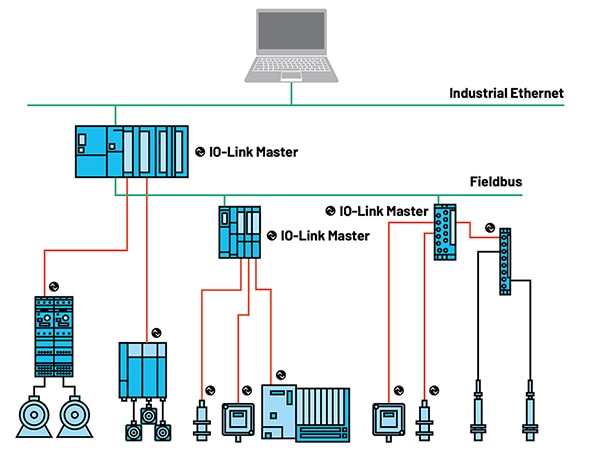 Figure 7: IO-Link works with a range of existing industrial architectures and can interface with existing PLCs or HMIs. (Image source: Analog Devices)
In recognition of the reality of industrial applications and installations, an IO-Link master or controller can automatically write the parameters of a replaced IO-Link sensor onto the new one. This feature enables quick and error-free exchange of sensors and shortens the time needed to restart system operation after sensor replacement.
IO-Link functionality in a system reduces maintenance, increases uptime, and transforms a manual sensor installation into one that allows a user to “plug-and-play and walk away.” The parameter settings can be downloaded from the controller to set up (or reconfigure) a device. This means a technician is no longer needed on the shop floor to do the initial setup, and machine downtime is reduced when it is required to reconfigure devices. IO-Link allows for continuous diagnostics, improved data logging, and increased error detection to further reduce operating costs.
Transceivers implement the physical link
Transceivers are needed to implement IO-Link at the physical level. The MAX14828ATG+ IO-Link device transceiver IC and complementary MAX14819ATM+ IO-Link master transceiver are highly integrated ICs, making them well-suited for robust sensor solutions in a space-saving footprint. In addition, there are on-board low-dropout (LDO) regulators for power, and LED drivers for local indicators.
The MAX14828ATG+ IO-Link transceiver integrates the high-voltage functions commonly found in industrial sensors (Figure 8). It features one ultra-low-power driver with active reverse polarity protection. An auxiliary digital input is provided to allow firmware updates through a UART interface. The device includes onboard 3.3 volt and 5 volt linear regulators for low-noise analog/logic supply rails.
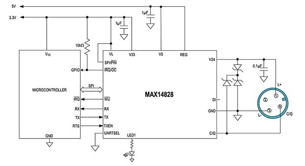 Figure 8: The MAX14828ATG+ IO-Link transceiver IC provides the critical interface between the sensor’s MCU and the physical link (connector and cable). (Image source: Analog Devices)
The MAX14828ATG+ can be configured and monitored either through the SPI interface or by setting logic interface pins. For application flexibility and tailoring, it features multiple programmable functions that allow the user to optimize operation and power dissipation for various loads and application scenarios.
Transient protection is enhanced by high-voltage tolerance, which allows the use of micro-sized transient voltage suppressor (TVS) devices. Other protection features include 65 volt absolute maximum ratings on interface and supply pins, glitch filters for improved burst resilience and noise performance, thermal shutdown, hot-plug supply protection, and reverse polarity protection of all sensor interface inputs and outputs. The transceiver is available in a 24-pin TQFN package measuring 4 × 4 millimeters (mm) or a 2.5 × 2.5 mm wafer-level package (WLP). Its operating temperature range is -40°C to +125°.
Designed to work with the MAX14828ATG+, but not limited only to that complementary IC, the MAX14819ATM+ is a low-power, dual-channel, IO-Link master transceiver (Figure 9). It also offers sensor/actuator power supply controllers and has two auxiliary digital input channels. It is fully compliant with the latest IO-Link and binary input standards and test specifications such as IEC 61131-2, IEC 61131-9 SDCI, and IO-Link 1.1.3.
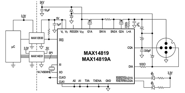 Figure 9: The MAX14819ATM+ dual-channel, IO-Link master transceiver is fully compliant with the latest IO-Link and other relevant standards and specifications. (Image source: Analog Devices)
The MAX14819ATM+’s integrated IO-Link framer eliminates the need for external UARTs. It is, however, configurable to use external UARTs. To ease the selection of the associated MCU, the master transceiver features frame handlers that work with UARTs and FIFOs. The MAX14819ATM+ also features autonomous cycle timers, thereby reducing the need for accurate controller timing. Integrated establish-communication sequencers also simplify wake-up management.
As with the MAX14828ATG+, the MAX14819ATM+ provides local power rails and features additional protection. It integrates two low-power sensor supply controllers with advanced current limiting, reverse-current blocking, and reverse polarity protection capability to enable robust low-power solutions. Additional protection includes reverse polarity protection and overvoltage tolerance on all interface pins, 65 volt absolute maximum ratings for TVS flexibility, and glitch filters for improved burst resilience. The MAX14819ATM+ comes in a 48-pin TQFN package measuring 7 × 7 mm, and it has an extended operating temperature range of -40°C to +125°C.
Evaluation kit for IO-Link design development
Getting hands-on experience with IO-Link in general, and the MAX14828ATG+ IO-Link transceiver in particular, is an important step in maintaining a design schedule. To this end, the fully assembled and tested MAX14828EVKIT# evaluation kit contains an IO-Link-compliant device transceiver with IO and SPI interface terminals (Figure 10).
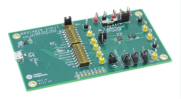 Figure 10: The MAX14828EVKIT# evaluation kit allows designers to initialize and evaluate the performance of the MAX14828ATG+ IO-Link transceiver quickly and with ease. (Image source: Analog Devices)
Operation of this evaluation kit requires a Windows-compatible PC connected via a USB cable. With the associated software and the addition of a user-supplied 24 volt/500 milliampere (mA) DC power supply, multimeter, function generator, and oscilloscope, the kit allows designers to configure, exercise, and assess the MAX14828ATG+. The associated documentation includes setup and operating instructions, a schematic diagram, a complete bill of materials (BOM), and images of all layers of the pc board layout.
Conclusion
Effective, accurate, and reliable temperature measurement in industrial settings using RTDs begins with a high-performance AFE for signal conditioning and digitization. Transferring this data to the system controller requires a suitable data link. As shown, sensor interfaces based on IO-Link, supported by suitable physical-level ICs, provide core functions as well as advanced configuration, fault detection and diagnostics, and management features to simplify and accelerate RTD smart factory deployments.
Recommended reading

Disclaimer: The opinions, beliefs, and viewpoints expressed by the various authors and/or forum participants on this website do not necessarily reflect the opinions, beliefs, and viewpoints of DigiKey or official policies of DigiKey.


