How to Make Smart Factory Actuators More Productive Using IO-Link
Contributed By DigiKey's North American Editors
2023-01-25
The shift to Industry 4.0, or the Industrial Internet of Things (IIoT), continues in order to achieve greater efficiency, safety, productivity, and lower overall cost. A critical element of this effort is device connectivity. This can be challenging as it requires the selection of a suitable communications standard and the design of related interfaces and associated software, all of which can slow down smart-factory deployments.
Designers of systems for industrial automation need a standard, reliable, efficient, and more modular approach to facilitate rapid and cost-effective deployments.
To address this issue, they can turn to IO-Link, a proven interface for use in smart factories. IO-Link is a bidirectional, point-to-point, single-drop digital communication interface (SDCI) that is governed by several standards, including IEC 61131-2, IEC 61131-9 (SDCI), and IO-Link 1.1.3.
This article briefly discusses the shift to smart factories and the challenges it presents to designers. It then provides an overview of IO-Link operation and how it simplifies smart-factory deployments. It presents examples of IO-Link devices from Analog Devices, including a slave device that can be used to replace pneumatic actuators and provide enhanced performance, a slave device with an integrated DC/DC converter, and a master device. Included are reference designs to quickly realize industrial actuators with IO-Link.
Simplifying the shift to smart factories
The shift to smart factories increases the need for a simple way to add intelligence at the edge for commissioning, monitoring and reconfiguring sensors and actuators. IO-Link’s simple installation and bidirectional communications capability support the deployment of edge intelligence. In one instance, IO-Link was credited for a 90 percent reduction in setup and commissioning times.
In practice, parameter settings can be downloaded over IO-Link to set up or reconfigure devices. This eliminates the need for intervention by a technician and reduces downtime. The smart diagnostics, error-detection, and data-logging capability of IO-Link can be used to gather real-time operational information across the factory floor, further reducing downtime.
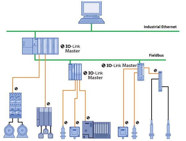
The architecture of an IO-Link system consists of point-to-point connections between the IO-Link master and various IO-Link devices. The use of standard M8 or M12 connectors and a 20-meter (m) long 3 or 4-wire cable simplifies system installation. IO-Link master devices usually have 4 or 8 ports, each connected to an IO-Link device. Each port can operate in standard input/output (SIO) mode or in bidirectional communication mode. Since it’s a point-to-point architecture, IO-Link is not a field bus, but it is compatible for use with field buses and industrial Ethernet and can connect to programmable logic controllers (PLCs) and human-machine interfaces (HMIs) (Figure 1).
 Figure 1: IO-Link is compatible with field buses and IEEE industrial Ethernet networks. (Image source: IO-Link Community)
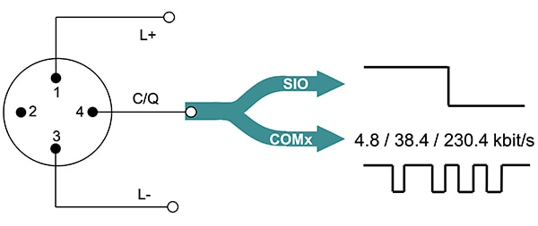
As well as operating in SDCI mode, IO-Link provides backward compatibility with the IEC 60974-5-2 standard for binary sensors. Basic point-to-point communication uses a 3-wire interface (L+, C/Q, and L-). In IO-Link mode, communication between master and slave devices is bidirectional with three possible transmission rates; COM1 is 4.8 kilobits per second (kbps), COM2 is 38.4 kbps, and COM3 is 230.4 kbps (Figure 2). An IO-Link master must support all three data rates so it can communicate with any connected slave device. Slave devices support only one data rate. Communication is with 24-volt pulses using nonreturn-to-zero (NRZ) encoding on the C/Q line. In IO-Link mode, pin 2 can be in digital input (DI) mode, digital output (DO) mode, or not connected. The IO-Link device (sensor or actuator) must function within 300 milliseconds (ms) after L+ exceeds an 18-volt threshold.
 Figure 2: IO-Link communication is bidirectional and can support 4.8, 38.4, and 230.4 kbps. (Image source: )
IO-Link device description
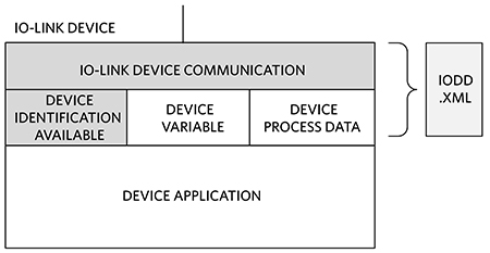
All IO-Link sensors and actuators have an IO-Link device description (IODD) file (Figure 3). The IODD is an xml file that provides the IO-Link master with the data it needs to identify and configure the device and interpret its data.
- IODD contents include
- Properties needed to support communication
- Device parameters
- Identification information
- Process and diagnostic information
- An image of the device and the manufacturer’s logo
- The structure of the IODD is outlined separately from IEC 61131-9
- A centralized database for IODD files is maintained by the IO-Link Consortium
 Figure 3: The IODD is an xml file that includes the information needed by the IO-Link master to identify, configure, and communicate with each slave device. (Image source: Analog Devices)
Data link and data types
Exchanges of messages between the IO-Link master and devices are managed by the data link (DL) layer. Messages are frames that are between 1 and 66 universal asynchronous receiver transmitter (UART) words long and are called ‘M sequences.’ Messages can relate to on-request data, system management requests and commands, and regular process data. The master includes a DL handler that takes care of errors and error messages and manages operating modes such as wake up, SIO, and COM rates, among others. When the master sends a request, devices are required to respond.
IO-Link communication can be synchronous or asynchronous. IO-Link masters and devices include process data handlers for synchronous communication, and an on-request handler for asynchronous communication of event, control, parameter, and index service data unit (ISDU) data. Asynchronous data is on-request and can contain the following:
- Configuration or maintenance information and control.
- Event-triggered, with three levels of urgency:
- Errors
- Warnings
- Notifications
- Page data to directly read device parameters
- Service data for large data structures
Integrating IO-Link into masters and devices can be complex. It’s necessary to fully implement the standards to ensure device interoperability and reliable system operation. To quickly integrate efficient and reliable IO-Link communications into smart-factory actuators, designers can use pre-engineered solutions for masters and devices. IO-Link device controller ICs have ultra-low-power drivers with active reverse-polarity protection and are available with and without an integrated DC/DC converter. They also have a serial peripheral interface (SPI) that supports extensive diagnostics. Dual-channel, IO-Link master transceiver ICs support low-power operation and simplify microcontroller (MCU) selection by including frame handlers with UART and first-in, first-out (FIFO) capabilities.
Replacing pneumatic actuators with IO-Link
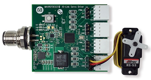
IO-Link offers a simple way to disrupt traditional approaches to process control and enhance factory operations by replacing pneumatic actuators with servo drives and sophisticated digital controls. For example, designers can use the MAXREFDES37# IO-Link servo drive reference design to speed time-to-market (Figure 4). This reference design provides 5-volt power and includes four pulse width modulation (PWM) outputs, plus four digital inputs to control up to four servo motors.
The board includes an M12-4 connector for connecting to an IO-Link master. The 3-pin headers support quick connection to standard 5 volt servo motors, one of which is included with the basic reference design. Connection to 5-volt digital inputs, power ground, and all four PWM channels is made using poke-in-wire terminal blocks. Technologie Management Gruppe Technologie und Engineering’s (TMG TE) IO-Link device stack is included. The MAXREFDES37# can be used in combination with the MAXREFDES277 two-channel IO-Link master in a Pmod form factor that includes a graphical user interface (GUI) program for easy verification using a Windows PC.
 Figure 4: The MAXREFDES37# has an M12 connector (left) for connection to an IO-Link master, and comes with a servo motor (right). (Image source: Analog Devices)
The MAXREFDES37# incorporates the MAX14821ETG+T IO-Link transceiver IC and the MAX17504ATP+T buck regulator DC/DC IC. The MAX14821ETG+T transceiver can be used with IO-Link devices and 24-volt binary sensors or actuators. All specified IO-Link data rates are supported, and the C/Q and DO drivers can source or sink up to 100 milliamperes (mA). The transceiver runs the DL layer protocol for interfacing with a microcontroller unit (MCU). Two internal linear regulators provide 5- and 3.3-volts of direct current (VDC) to power sensors and actuators, and 24-volt digital inputs and outputs are also included. Integrated DO and C/Q drivers can be independently configured for push-pull, low-side (NPN), or high-side (PNP) operation. The transceiver can be configured and monitored through an SPI.
The on-board MAX17504 synchronously rectified step-down DC/DC converter operates over an input range of 4.5 to 60 VDC. It has an output voltage range from 0.9 volts to 90% of the input voltage and delivers up to 3.5 amperes (A). Regulation accuracy is ±1.1% from -40 to +125 degrees Celsius (°C). It has a peak efficiency >90% and a shutdown current of 2.8 microamperes (μA).
Transceiver for master or devices with integrated DC/DC
For designers of IO-Link masters and devices, there is the MAX22514. A high level of integration—including a DC/DC buck regulator, two linear regulators, and integrated surge protection—as well as low power dissipation and a choice of a wafer level package (WLP) (2.5 millimeters (mm) x 2.6 mm) or a thin quad flat pack (TQFN) package (4 mm x 5 mm), makes this transceiver well-suited to space-constrained industrial IO-Link applications (Figure 5).
For example, part number MAX22514AWA+ is in a WLP. Its SPI supports configurability and diagnostics, and it also supports COM1, COM2, and COM3 data rates.
 Figure 5: The MAX22514 transceiver is highly integrated and suited for use in IO-Link masters and devices. (Image source: Analog Devices)
To shrink development time, designers can use reference designs such as the MAXREFDES278#. This is an 8-channel solenoid actuator reference design based on the MAX22514 IO-Link transceiver that demonstrates the MAX22200, a 1 A octal integrated serial-controlled solenoid driver with integrated field effect transistors (FETs). The reference design includes an integrated DC/DC buck regulator. Windows compatible software is included that provides a graphical user interface (GUI) for exploring the features of the MAX22514. A USB-A to micro-B cable is used to connect the eval board to a PC.
Dual-channel master
When a dual-channel IO-Link master is needed, designers can turn to the MAX14819ATM+ transceiver, which includes two auxiliary digital input channels. An integrated IO-Link framer eliminates the need for external UARTs, and the integrated cycle timer unburdens the MCU from needing to handle timing-critical tasks. This transceiver can be used in combination with the MAX14931FAWE+ and MAX12930EASA+T digital isolators. The MAX14931FAWE+ has four channels for transmitting digital signals in one direction. The MAX12930EASA+T has two channels for data transfer. The MAX14819EVKIT# evaluation kit is available for the MAX14819A and includes the MAX14931 and MAX12930 digital isolators (Figure 6).
 Figure 6: The MAX14819EVKIT# dual-channel IO-Link master evaluation kit includes the MAX14819 transceiver and the MAX12930 and MAX14931 digital isolators. (Image source: Analog Devices)
Conclusion
To reap the benefits of the IIoT and Industry 4.0, sensors and transducers need to be deployed rapidly and cost effectively. To that end, IO-Link provides industrial automation system designers with a standard, reliable, efficient, and modular approach. As shown, using off-the-shelf components, designers can use IO-Link to add intelligence at the edge for commissioning, monitoring, and reconfiguring sensors and actuators.
Recommended reading

Disclaimer: The opinions, beliefs, and viewpoints expressed by the various authors and/or forum participants on this website do not necessarily reflect the opinions, beliefs, and viewpoints of DigiKey or official policies of DigiKey.


