IO-Link 1.0 to IO-Link 1.1
Contributed By DigiKey's North American Editors
2020-11-03
Widely used for decades in industrial I/O, recent years have brought a dramatic rise in IO-Link adoption. As explained in the DigiKey article “Comparing IO-Link 1.0 and 1.1”, the International Electrotechnical Commission IEC 61131-9 open standard (branded IO-Link) imparts easy-to-use connectivity to automation components. It’s a single-drop digital communication interface (SDCI) to network small sensors and actuators called field devices or secondaries to IO-Link controller hubs or primaries and onward to the rest of the automation installation. One of IO-Link’s benefits is that it allows use of generic unshielded cable (to 20 m long with three to five conductor strands) for these connections.
This article will more fully explain the three IO-Link features that are new to its version 1.1:
- IO-Link 1.1 allows the backup of data so that plant personnel can save and reuse device parameters
- IO-Link 1.1 can process data widths to 32 bytes per port
- IO-Link 1.1 allows 230.4 kbaud data rates from IO-Link 1.1 primaries
 Figure 1: IO-Link communication allows R.A JONES to more closely monitor sensors for performance, maintenance, and changing of parameters via recipes. That’s according to innovation engineer manager Nate Smith. In fact, IO-Link is fast becoming a leading industrial standard for communication with field devices (secondaries) in automation. (Image source: R.A JONES)
IO-Link 1.1 as Parameter Assignment Server
Control integration of IO-Link components is done through configuration software that leverages the standardized IO device-description (IODD) files associated with each IO-Link component. These IODD files (which store the component’s model, operating ranges, data to support diagnostic functions, and symbol for display on HMIs and GUIs) are .xml files that are supplied by the component manufacturer to support IO-Link V1.0 and V1.1 via their own websites and ioddfinder.io-link.com.
What’s new in IO-Link 1.1 is the ability of some IO-Link 1.1 primaries to locally store IODD files and complementary data — to provide parameter assignment server functions for other devices on the network. Before this feature (and in legacy IO-Link installations) end users needing to swap in a new or replacement field device were forced to first configure that device — usually by plugging it into a PC’s USB port and manually executing setup through software.
Yet another benefit to this aspect of 1.1 is how end users can now (in many instances) hotswap comparable IO-Link edge devices from different manufacturers — making a wider selection of basically interchangeable devices more accessible. That’s particularly useful for emergency replacement of failing or damaged sensors on high-volume production lines.
Specifics of the Higher IO-Link 1.1 Communication Speed
The other IO-Link feature new to 1.1 is COM3 — the communication mode with a rate to support more advanced field-device functionalities. COM3 SDCI communication’s data rate is specified to be up to 230.4 kbit/sec (here 230.4 kbaud as well). That means the newest IO-Link iteration (1.1.3) comes with improvements to address the last lingering objection to IO-Link — that the standard has insufficient speed for modern automation.
More specifically, 1.1.3 can impart cycle times supporting real-time communications for the cyclically transmitted process data described in the previous DigiKey article on this subject; even to sub-msec cycles in some cases. Process data transmitted for real-time bandwidth (in kilobytes per second (kB/sec)) depends on the time it takes for the primary to request a message from the device, a communication-direction switch delay, the time it takes for the field device to respond, and another communication-direction switch delay.
It helps to have some background on the physical microcontroller circuits (in some instances standalone ICs) to understand how IO-Link components execute these communications. Within the primary and its secondary field devices are circuits called universal asynchronous receiver-transmitters (UARTs) that bundle or frame data into packets for transmission. These frames are 11 bits long — with one bit used to communicate start, eight bits (also called an octet in IO-Link specifications and official literature) used to carry actual process data, and two more used to communicate parity and stop.
 Figure 2: The MAX14827AATG+ from Maxim Integrated is a low-power dual-driver IO-Link transceiver for integration into IO-Link devices. A three-wire UART interface allows IO-Link connectivity with the microcontroller UART, and a multiplexed UART/SPI allows the use of one serial microcontroller interface for shared UART and SPI functions. (Image source: Maxim Integrated)
According to Table 9 of the June 2019 IO-Link 1.1.3 Specifications, it takes an IO-Link COM3 arrangement 4.34 µsec to transmit each bit. That time plus delays between packets in both the primary and secondary (up to 4.34 µsec and triple that respectively) as well as 4.34 µsec to 43.0 µsec for the communication-direction switch delay make for a worst-case sub-msec data-transmission rate that is still quite sufficient for demanding industrial applications.
The wildcard (having dramatic influence on real-time bandwidth) is the message-sequence type chosen for the IO-Link network. Different sequence types accommodate various amounts of acyclical or on-demand data transmission. So to estimate the real-time bandwidth of an IO-Link arrangement, calculations must account for both the process data and acyclical data allowed by the system messaging. Some types define fixed process and acyclical on-demand octet values while others allow the supplier or user to set process-data octets to between one and 32, and acyclical data octets to either 1, 2, 8 or 32. In short, systems that need to move less data have faster cycle times.
Analysis of all the above factors yields real-time bandwidth — defined by process data (only) transmitted (in kbits) divided by total calculated cycle time in kbit/sec. For example, with only one acyclical data octet (for 1·8) and 32 process-data octets (for 32·8), cycle time is just over a couple milliseconds and bandwidth exceeds 100 kbit/sec.
All new IO-Link 1.1 primaries support COM3 and the automation components leveraging this data rate — and automatically adapt to the rates its connected secondaries happen to use. In fact, it’s common to have field devices with various cycle times run off one primary to allow use of sensors and actuators of various sophistication levels, as well as incremental design upgrades. Actuators employing the 230.4 kbaud data rate of COM3 (usually with the Class B port arrangement covered in this article’s next section) include fluid-power as well as electromechanical components — including pneumatic valves, linear cylinders, and manifolds as well as small field devices based on step motors. Sensors that most commonly use COM3 include position and displacement sensors as well as color, temperature, and pressure sensors, all of which are the most common in process control. Select mechanical switches also leverage this COM3 communication mode.
 Figure 3: Panasonic's intelligent HG-C1000L Series sensors use the COM3 connections of IO-link to support remote monitoring and preventative maintenance routines. Onboard sensor logic can detect normal, error, caution, and alarm states. These sensors also provide a means to quickly and remotely reconfigure sensor settings and operations when warranted. (Image source: Panasonic Industrial Automation Sales)
IO-Link 1.1 Physical Connections (Including Data Ports)
Now consider the data widths of IO-Link — to 32 bytes per port for process data. All activated ports on IO-Link primaries are set to handle digital output and input or run as an IO-Link point using a UART in half-duplex mode (so that bits of data are sent and received in single-bit sequences). A typical four-port or eight-port IO-Link primary might directly connect to several field devices or serve as an intermediary hub — and transmission width depends on this primary. Connections to a typical IO-Link field device include supply conductors L+ and M as well as C/Q1 conductors, with the latter carrying process data as well as data for parameterization, configuration, and diagnostics.
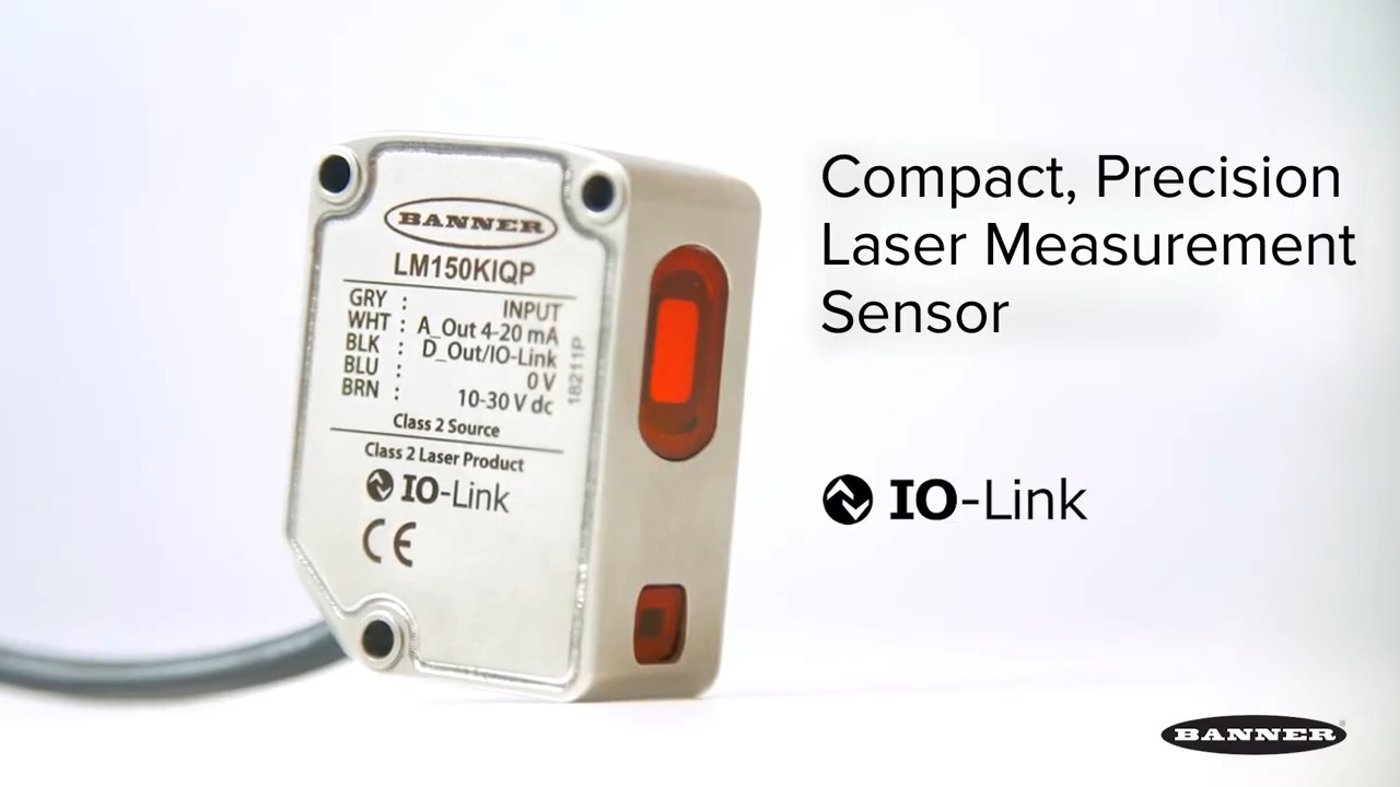
 Figure 4: Intelligent sensors such as this SICK pressure sensor with IO-Link (allowing connections via a four or five-pin M12) can avoid the downtime and errors associated with manual reprogramming. That’s because they allow parametric edits and reconfiguration via the machine’s PLC. Notice the L+ and M as well as C/Q1 connections of the IO-Link connector. (Image source: SICK)
Slightly complicating matters here is that IO-Link specifications allow both Class A and Class B ports on primaries and secondaries. Class-A ports as defined by IEC 60947-5-2 are not to be confused with A-coded M12 connectors as defined by IEC 61076-2-101. Read more about ubiquitous M12 connectors in the context of IO-Link in the DigiKey article “The Fundamentals of IO-Link”. In short, IO-Link connector pins 2 and 5 are sometimes used (and that use varies) while pins 1, 3 and 4 are always used (with use only varying for the latter). Class A arrangements (based on four-pin M5, M8, or M12 connectors) allow for more I/O variations and even high-current output for driving actuators. In contrast, class B arrangements are always five-pin M12 connections.
No matter the class, female connector receptacles are located on the primary and male connector pins on the secondary field device.
The 32 bytes per port for process data is just a maximum used for the most advanced IO-Link-connected sensors and actuators; and in fact, the data width of a very simple IO-Link secondary such as a switch can be just one bit. Where the set data width is insufficient for the application, some IO-Link primaries allow for fragmented process-data transmission. Other data-capacity expansion schemes of IO-Link include multiple uses of the pin-4 conductors for bidirectional IO-Link and switching communications as well as dual-channel data transmission running parallel to pin-4 IO-Link data. For the latter, the pin-2 conductor may carry device-specific I/O or switching signals (often though not always associated with status monitoring) and freeing the IO-Link channel to carry complementary signals. Such IO-Link dual-channel data transmission allows real-time communications sans the delays associated with remote PLCs (including cycle times) which in turn support applications necessitating prompt analysis of and response to machine or device conditions.
Conclusion
The three IO-Link features new to version 1.1 include the backup of data (for the saving and reuse of device parameters); the ability to process data widths to 32 bytes per port; and 230.4 kbaud data-transmission rates from primaries. These features have only accelerated the adoption of IO-Link 1.1 for industrial automation.
Disclaimer: The opinions, beliefs, and viewpoints expressed by the various authors and/or forum participants on this website do not necessarily reflect the opinions, beliefs, and viewpoints of DigiKey or official policies of DigiKey.