Use a Cellular Module to Connect a Maker Project to the IoT
資料提供者:DigiKey 北美編輯群
2017-10-04
Makers and professional engineers alike are increasingly turning to wireless connectivity to enhance the functionality of their projects and connect them to the Internet of Things (IoT). The single board computers (SBCs) that such projects use often integrate Bluetooth and Wi-Fi, but for longer range, cellular interfaces are a good alternative.
While cellular modems offer greater range, the downsides are increased complexity, size, cost, power draw, and a requirement to satisfy regulations governing licensed spectrum allocations.
This article considers the advantages of using a cellular module for maker project wireless connectivity, and describes the hardware, software, and regulatory challenges that arise during implementation.
The article then provides solutions that help overcome the challenges that makers and designers may face when taking advantage of cellular-based, long-range RF connectivity.
The advantages (and drawbacks) of cellular connectivity
While changes are planned, today’s Bluetooth low energy and Wi-Fi technologies don’t support direct connectivity to the IoT. In contrast, a smartphone is interoperable with Bluetooth low energy, Wi-Fi, and the (cellular) IoT. Hence it can be used as a gateway between wirelessly connected devices such as a maker project SBC and the cloud. Similarly, a Wi-Fi router and cable modem can form a gateway for Wi-Fi enabled SBCs (Figure 1).

Figure 1: Wireless technologies such as Bluetooth low energy (formerly known as Bluetooth Smart) and Wi-Fi require routers or gateways to access the Internet, restricting sensor mobility and range. Cellular modules eliminate the router or gateway by directly connecting to other IP-enabled devices. (Image source: Nordic Semiconductor)
For many maker applications, IoT connectivity via a gateway is a satisfactory solution. However, if the sensor moves out of wireless range of the gateway (beyond 30 to 100 meters for both Bluetooth low energy and Wi-Fi) connectivity is lost. Such a restriction prevents makers from developing projects based in remote locations, or those that are constantly on the move. Cellular modules provide an answer.
Cellular modules are not new. A large industry has grown up around the technology for servicing the machine-to-machine (M2M) applications. For example, vending machines in remote locations are often connected to the company’s computers via a cellular link. Given that designing a cellular modem from scratch is extremely difficult, the solution comes in the form of plug-and-play modules that are tested, verified, and certified.
Cellular module makers now offer products specifically targeted at the maker that are designed to be compatible with popular SBCs from suppliers such as Microchip Technology, Arduino, and Adafruit. Using a cellular module, a maker project SBC can send data directly to another remote Internet-connected device, such as the maker’s smartphone (when they are away from the SBC) or a cloud server, without needing a gateway. Moreover, a cellular modem offers a range of up to tens of kilometers, extending the range of wireless maker projects beyond the home. Cellular modems also dispense with the need for inconvenient password entry to add the wireless device to a LAN.
Cellular communications use licensed frequencies. While there is a fee for use, the upside is they are tightly controlled and hence relatively free of the congestion and associated interference that can trouble a license free band, such as 2.4 GHz. To gain access to the network, the process is the same as that adopted by the mobile phone; users subscribe to a local carrier. They then obtain a subscriber identity module (SIM) that upon insertion authenticates the module, enabling a set amount of data upload and download according to the terms of the contract.
In addition to the license fees, there are some other drawbacks to cellular connectivity. The modules are relatively large, heavy, expensive, and power consumption is much greater than Bluetooth low energy or Wi-Fi. Moreover, connecting directly to the cellular network is more involved than connecting to a smartphone or router.
In addition, there are several cellular technologies (for example, GSM, GPRS, and CDMA), several generations of each technology in commercial use (2G, 2.5G, 3G, and 4G), and dozens of cellular bands across the globe. As a result, selecting a cellular module for a specific location requires careful consideration.
Note that 2G modules are generally less expensive, but be careful: operators are gradually phasing out this older technology, though it may take many years to do so.
Cellular modules pervasive for maker projects
Cellular module in hand, all a maker needs to do now is ensure the module’s physical interface matches that of the target SBC, establish the carrier contract, insert the SIM, and select the appropriate antenna.
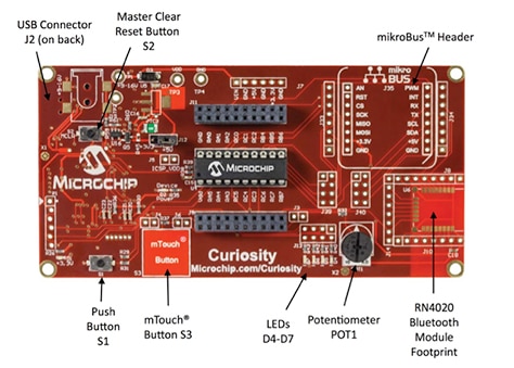
Keen to tap into the burgeoning maker market, cellular module makers provide units that interface directly with popular SBCs either via header pins or cables. For instance, MikroElektronika supplies a range of cellular modules from its Click Board family that interface directly with Microchip’s Curiosity SBCs, via mechanical connectors.
The SBCs use 8, 16, or 32-bit PIC microcontrollers from Microchip and include an integrated programmer/debugger with USB interface; mTouch buttons, analog potentiometer, switches, and RGB LEDs; and, crucially, support for MikroElektronika’s mikroBUS interface (Figure 2).
The SBCs can be programmed using Microchip’s MPLAB X Integrated Development Environment (IDE) and the 8 and 16-bit microcontroller versions can be programmed using the MPLAB Xpress IDE, which suits makers who are unfamiliar with PIC microcontrollers.

Figure 2: Microchip’s Curiosity SBC uses a mikroBUS interface, making it simple to attach a 2.5G GSM/GPRS Click Board cellular module. (Image source: Microchip Technology)
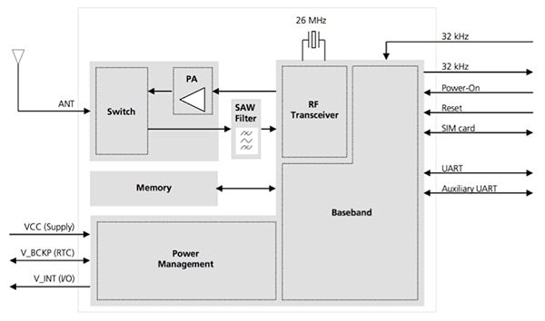
MikroElektronika’s GSM 4 click attaches to the Curiosity SBC via header pins and takes 3.3 or 5 volts directly from the SBC. The cellular module is based on a u-blox SARA-G3 series 2.5G GSM/GPRS modem that integrates an RF transceiver and a power amplifier for greater range (Figure 3). The SARA-G3 is specifically designed for M2M applications and so works well for makers wanting to send modest volumes of sensor data across the cellular IoT.
The cellular modem includes IPv4 and IPv6 communication protocols making it interoperable with any other IP-enabled device on the Internet. A quad-band version of the SARA-G3 is available which operates on the 850 and 1900 MHz bands used in North, South, and Central America, and the 900 and 1800 MHz frequencies used in Europe, Africa, the Middle East, and Asia.

Figure 3: MikroElektronika’s GSM 4 click is based on the u-blox SARA-G3 modem shown here. The modem integrates a power amplifier (PA) to boost range. (Image source: u-blox)
In addition to sending and receiving data, the GSM 4 click can respond and react to phone calls or messages. It includes an antenna connector (but no antenna) and a SIM card socket. Communication with the PIC microcontroller is through a UART connection or USB port.
For its Click Board products, MikroElektronika offers the mikroC IDE. This includes Visual TFT, a ‘what-you-see-is-what-you-get’ graphical user interface design tool, and a fully featured C compiler.
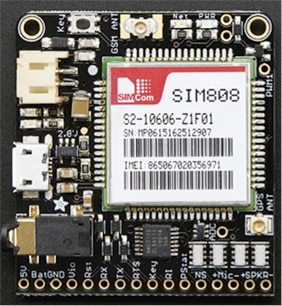
Adafruit’s FONA 808 Cellular + GPS Breakout is a good option for makers familiar with Arduino SBCs (but can be used with almost any microcontroller) running from a 3 to 5 volt supply with a UART (Figure 4). The module is a quad-band (850/900/1800/1900 MHz), GSM 2G radio with GPS and GPRS send and receive data capability. A 16-pin header must be soldered into the breakout pinholes to attach the module to, for example, an Arduino SBC.

Figure 4: Adafruit’s FONA 808 works well with Arduino SBCs. Like other cellular modems, it requires a SIM card and antenna. (Image source: Adafruit)
If the developer wants to take advantage of the speed and bandwidth advantages of 3G, a good option is the Particle Electron 3G Kit from SparkFun Electronics. The kit comes in two versions: one for 850/1900 MHz operation, and one for 900/1800 MHz operation.
The kit not only includes the cellular module (another u-blox SARA-powered unit) but also integrates an STMicroelectronics STM32 ARM® Cortex®-M3 microcontroller, allowing it to operate independently of an SBC, if preferred. The Electron Kit comes with Particle’s IDE and cloud platform for programming the device. Particle’s IDE is similar to the Arduino development platform.
Unlike some other cellular modules targeted at maker applications, the Particle Electron Kit comes complete with SIM card, three month 1 Mbyte per month data plan, 2000 mAh Li-Po battery (the device can also be powered from an external power supply), antenna, and breadboard for prototyping.
Communicating with cellular modems
Some coding skills are needed to get a cellular module to connect and receive/transmit data, but these should not be beyond the skills of a maker familiar with an IDE such as Arduino’s to program a microcontroller.
The SBC typically communicates with the cellular module using a UART serial link. AT commands are the standard means of controlling a cellular modem. The commands comprise a series of short text strings that can be combined to produce operations such as dialing, hanging up, and changing the parameters of the connection.
There are two types of AT commands: Basic commands are those that don’t start with “+”. “D” (Dial), “A” (Answer), “H” (Hook control), and “O” (Return to online data state) are examples of basic commands (Listing 1).
void gsm4_init( void )
{
engine_init( gsm4_evn_default );
at_cmd_save( "RING", 1000, NULL, NULL, NULL, gsm4_ev_ring );
at_cmd( "AT" );
at_cmd( "AT+CSCS=\"GSM\"" );

at_cmd( "AT+CMGF=1" );
}
Listing 1: This code example uses AT commands in a test routine to reject calls received by a cellular module. (Code source: MikroElektronika)
Extended commands are those that do start with +. For example, “+CMGS” (Send SMS message), “+CMGL” (List SMS messages), and “+CMGR” (Read SMS messages). Note that GSM only uses extended commands.
A “final result” code marks the end of an AT command response. It’s an indication that the GSM module has finished the execution of a command line. Two frequently used final result codes are “OK” and “ERROR”. The OK code indicates that a command line has been executed successfully. The ERROR code indicates that an error occurs when the cellular module tries to execute a command line. After the occurrence of an error, the cellular module will not process the remaining AT commands in the command line string.
AT command syntax differs depending on the module producer. In addition, a module may only be able to respond to a subset of the AT commands, although cellular modules designed for wireless applications typically have better support for AT commands than ordinary mobile phones. Advice should be sought from the individual module manufacturer’s AT commands reference guide, which will also inform the maker how to format the AT commands, and how to interpret the cellular module’s responses.
There are, however, four basic AT commands to which every modem responds:
‘Set’ commands [AT+<parameter>=<value>] are used to store values.
For example, AT+CREG=1 // Set Command
‘Get’ commands [AT+<parameter>?] are used to read stored values.
For example, AT+CREG? // Get Command
Test commands [AT+<command>=?] are used to determine the range of values supported.
For example, AT+CREG=? // Test Command
Execution commands [AT+<parameter>] are used to invoke a particular function of the cellular modem.
For example, AT+CREG // Execution Command
Other common (and useful) AT commands include:
- Mobile network registration status (AT+CREG)
- Radio signal strength (AT+CSQ)
- Battery charge level, and battery charging status (AT+CBC)
- Establish a data connection to a remote modem (ATA, ATD, etc.)
- Perform security related tasks, such as changing passwords (AT+CPWD)
- Get or change the configurations of the cellular module. For example, change the GSM network (AT+COPS) or radio link protocol parameters (AT+CRLP)
The sending and receiving of AT commands is achieved via the serial communications link by the particular SBC, IDE, and programming language chosen. The cellular module is unaware of what’s on the other end of the serial link and simply responds to the AT commands transmitted across the link. (Similarly, the SBC is unaware that it’s connected to a cellular module.)
Cellular modules typically feature multiple UART I/O, some with dedicated functions. Pin 14 of the GSM 4 click, for example is a dedicated data transmit output, while pin 13 is a dedicated data receive (Figure 5).

Figure 5: Cellular modems typically incorporate multiple UART I/O, some with specific functionality. (Table source: MikroElektronika)
When employing the Curiosity SBC and GSM 4 click cellular module, for example, the agnostic nature of AT commands allows the developer to employ either Microchip MPLAB X or MPLAB Xpress, or MikroElektronika mikroC IDEs. The FONA 808 can be programmed using the Arduino IDE once the user has downloaded the Adafruit FONA library from the GitHub repository, and moved it to the Arduino library folder.
AT commands for virtually any operation of a cellular module can typically be found in the manufacturer’s open source code library. MikroElektronika’s can be found at libstock.mikroe.com, while Adafruit’s is located in the GitHub repository. Other sources of AT commands come from the cellular modem manufacturers. u-blox, for example, has produced an application note (Reference 1) for AT command examples that cover virtually all usage scenarios, while SIM Tech AT commands are listed in a manual available from Adafruit.
Conclusion
Cellular modules provide a “plug-in” solution for a maker project requiring IoT connectivity regardless of where the project is situated (provided the project is in range of a cellular base station). There is a range of mature 2G, 2.5G, and 3G cellular modules ideally matched to popular maker SBCs, and hardware considerations extend only to selecting and fitting an appropriate antenna, mechanical connector, and battery. Because the cellular network is licensed, a SIM card and data contract will also be required.
References
- “AT Commands. Examples for u-blox cellular modems”, Application note, revised September 2016.
- Bluetooth 4.1, 4.2 and 5 Compatible Bluetooth Low Energy SoCs and Tools Meet IoT Challenges

聲明:各作者及/或論壇參與者於本網站所發表之意見、理念和觀點,概不反映 DigiKey 的意見、理念和觀點,亦非 DigiKey 的正式原則。


