Mfr Part # 5359
DIY MAGN CONN R/A 1=BOTH HALVES
Adafruit Industries LLC
License: See Original Project LEDs / Discrete / Modules Microcontrollers Programmers Proximity Solder / Desoldering Touch
What's up, everyone! Zach, your Byte Sized Engineer here. If you caught part one of this series, you saw the birth of my PCB tile-based board game – a little prototype I whipped up. I decided magnetic connectors were the way to go, but let's be honest, they weren't quite ready for prime time. We needed more patterns, a complete set of tiles, and a few adjustments to the original design. So, in this post, we're diving deep to see if we can push this project over the finish line.
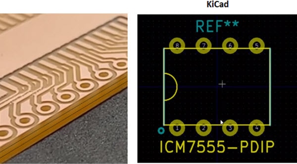
Looking back at our first attempt, a few things needed an upgrade. I mentioned these in part one, but let's recap. The silkscreen needed to extend right to the edge of the board to make the pathways pop and a lot clearer for players. The magnetic connectors had a bit too much wiggle room. When I soldered them on, a noticeable gap was created, so I’ll use smaller holes for a snugger, cleaner fit. Remember those awesome reverse-mountable RGB LEDs from my macro pad project? Yep, they're making a comeback! Switching to these means all the components can be placed on one side of the board, making assembly significantly easier.
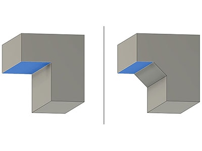
Take a look at how these changes appear on the updated PCB – the thicker silkscreen and those reverse-mount LEDs look pretty sweet, right? Now for the fun part: figuring out all the possible path patterns we can create with three paths on our hexagonal tiles. I spent a good chunk of time pondering this, and I think I've cracked it. Imagine a path starting on one edge. It can really only go to three main places:
Adjacent Edge: The one right next to it.
Skip an Edge: Jumping over one to the next.
Opposite Edge: Straight across.
The other two edges are just repeats of these, so we've got our three core path types. Now, the challenge is to find all the unique combinations of these without any repeats. Time to bust out the graph paper (and, let's be honest, a spreadsheet – I am an engineer, after all!). After mapping everything out and weeding out duplicates and impossible combos, I landed on five distinct patterns:
Adjacent, Adjacent, Adjacent
Adjacent, Opposite, Adjacent
Opposite, Opposite, Opposite
Opposite, Skip, Skip
Adjacent, Skip, Skip
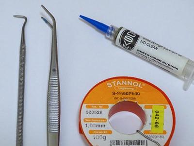
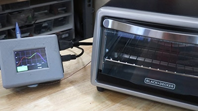
With these five patterns locked in, my team and I got to work designing a separate PCB for each one. After the designs were finalized, it was time to order the PCBs and all the necessary components. Once everything arrived, I fired up the solder reflow oven I built in a previous video and got to assembling. The process involved applying solder paste, carefully placing each component, and then sending them through the reflow oven. Lastly, I added the magnetic connectors, but there was an issue! I ran short on connectors. Time for a little "creative" sourcing. I decided to reclaim the connectors from my prototype boards. Luckily, I had a new toy to play with: the Hakko FR-301 desoldering tool. This desoldering vacuum made quick work of heating up the solder and sucking it away, making connector removal a breeze. Seriously, without this tool, I would've been in a world of hurt trying to melt multiple joints at once with multiple irons. Those tighter through-holes for the connectors worked like a charm! No more wiggle room, just perfect alignment, and a solid connection.
We're in the home stretch! It's time to breathe some life into these boards with some programming. I spent a good amount of time in the Arduino environment, figuring out the best approach. With five different board patterns, each with its own microcontroller, my first thought was to create five separate firmware versions. But let's be real, that would be a maintenance nightmare if I needed to make changes down the line. I put in a little extra effort up front to build a unified codebase. I created a “Tile” structure as the main framework, with nested “Path” and “Connector” structures. This allows me to assign the right GPIO pins for each path on all five patterns. Then, using preprocessor directives, I can simply select the tile type at the beginning of the code. This means only the relevant code gets compiled for each board. It's a slick way to manage everything, just comment or uncomment a line, and boom, the right firmware is ready to go. If you're curious and want a closer look at the code, you can find it in my GitHub repo here, so feel free to dive in! With the code sorted, it was time to program all 20 of my newly assembled boards. Using the UPDI programmer from the last video and a handy exposed pad on the board, I flashed each tile with its designated firmware. A quick uncomment, an upload, and I had a programmed tile!
The tiles were programmed and ready to go, but something was missing. The exposed components on the bottom didn't exactly scream "finished game." So, it was back to the computer, this time to design a 3D-printed bottom cover. I imported the PCB into Fusion, created a sketch, and extruded it to fill the negative space; however, I encountered a snag. There are no mounting holes! I needed a clever way to attach the cover. That's when I noticed the unique profile of the magnetic connectors. They have a slight curve on the front, providing just enough of a lip for a 3D printed part to snap onto. I designed a feature to "hug" the underside of the connector, and after a few test prints, I had a winner! It snapped on perfectly with a satisfying click – no wiggle room, just a clean, polished look. I even considered adding a top layer to diffuse the LEDs, but honestly, it didn't significantly enhance the overall experience, so I decided to keep it simple.
With the tiles fully assembled and looking sharp, it was finally time to play! I roped in Pat, our cameraman, for the inaugural game of what I'm calling "Pixel Path." The goal is to create the longest complete path. We took turns drawing tiles and extending our own paths. You can't directly interfere with your opponent's path, but your moves can definitely influence the board. It was an interesting first game, full of twists, turns, and some unexpected path-crossing. We managed a draw! It was a blast, but it also highlighted some areas for improvement. We also explored what a "win" looks like (flashing LEDs!) and what happens when paths collide (alternating colors and a draw).
Now, I need to come clean... You might be wondering how these tiles are getting their power. While I had grand visions of LiPo batteries or wireless power, for this version, I took a little shortcut. The starting tile has a couple of wires soldered to the bottom, running through an existing hole in my workbench and connected to a benchtop power supply. A little bit of "movie magic," if you will! In the future, I'd love to develop a wireless solution for a more portable gaming experience. A possible alternative for someone unwilling to drill a hole through their benchtop would be to use a flat-flex cable.
This has been an incredibly fun and challenging project, and I'm thrilled with the outcome. But I'm not done yet! I think there's still room to develop the game further and add some more interesting mechanics. As always, thanks for joining me on this engineering adventure.