Mfr Part # ATTINY3217-MNR
IC MCU 8BIT 32KB FLASH 24VQFN
Microchip Technology
License: See Original Project LEDs / Discrete / Modules Microcontrollers Laser Cutters Programmers
I've got a confession to make. When I'm not knee-deep in circuits and code, you can probably find me around a table covered in board games. For a long time now, a little project has been brewing in the back of my mind – designing a board game from the ground up, but not just any board game. I wanted to create a tile-based game where the tiles electronically interact with each other the moment they snap together. Think of those satisfying magnetic tiles you might have played with as a kid, but with a whole lot more going on under the hood. Imagine a set of tiles, each equipped with interactive LED paths. As players take their turns, they place their tiles, and depending on their positions and connections, the lights would dynamically respond. Pretty cool, right?
Now for the million-dollar question: How should these tiles talk to each other? Magnets are great for that satisfying "click" as they connect, but they don't exactly carry data. Initially, my mind jumped to solutions like RFID or NFC. While definitely viable, they felt a tad over-engineered for this initial exploration. Then, I considered infrared LEDs, reminiscent of your trusty old TV remote. However, I quickly dismissed that due to potential issues with ambient light and overall reliability. That's when I stumbled upon something truly promising on the DigiKey website… magnetic connectors! These aren't just your run-of-the-mill magnets. These are the same clever connectors you might remember from older MacBooks. These little guys are the key to the project's success because they not only snap together with a satisfying force but also provide a physical pathway for electrical communication.
With the connection method sorted, the next puzzle I needed to solve was the tile shape. Should I do squares, triangles, or octagons? The possibilities seemed endless. Instead of getting bogged down in theoretical debates, I decided the most ByteSized Engineering approach was to prototype it out. I fired up the laser cutter and churned out a few different shapes with small holes to press-fit the magnetic connectors. First up were the squares. For this initial test, I wasn't entirely confident in the friction-fit connectors, so I added a tiny dab of hot glue to keep them in place, and just to be clear, they aren't going to be wooden tiles in the final version. Picture them as circuit boards. Each tile will click into place, packed with electronics and lights, ready to interact as you build out the game board. Just holding this prototype in my hand is getting me seriously excited. The square tiles work really well. The magnetic connection is solid and satisfying. In fact, I think most of the shapes I cut would work, with one notable exception: the triangle, and here’s why. These magnetic connectors come as mating pairs. One connector features spring-loaded pogo pins, while the other has flat pads. You can't connect two of the same type together. This makes a triangular arrangement tricky, as there wouldn't be a consistent way for all sides to connect. So, the triangle is a no-go, and I have to say, the way these hexagons are coming together is really appealing. In the end, I think I've settled on the hexagons. As this game is played out, I think the honeycomb pattern is going to look fantastic. Plus, let's be honest, everyone knows hexagons are the bestagons! Now I can finally start thinking about the circuit board design.
I need to decide what these tiles are actually going to do. The core idea for the gameplay is turn-based. As each player adds their hexagonal tile to the growing board, a pathway of light will illuminate across the connected tiles. The initial thought was to have a central starting tile with a microcontroller that would orchestrate all the light patterns. As new tiles were placed, this central brain would tell them what to do. However, I quickly realized that managing communication with a potentially large and sprawling board could get complicated fast. Keeping track of every tile's position and its neighbors seemed like a recipe for a messy codebase. So, I pivoted to a more decentralized approach. I decided to put a microcontroller on each individual tile. The beauty of this is that each tile only needs to be aware of its immediate neighbors. The firmware on each tile can then independently decide what lights to illuminate based on the connections it detects. It's ironic, now that I think about it, that this is shaping up to look like a beehive, because it won't behave like one! There's no central queen bee calling the shots.
Let's take a peek at the schematic. In the top left corner, I opted for the ATtiny3217 microcontroller. It offered a good balance of GPIO pins and program memory for my needs. In the top right corner, you can see the magnetic connectors. Below, we have three distinct chains of addressable RGB LEDs. Why three? Considering our hexagonal tile, each path requires a unique start and end point. A hexagon has six sides, which means there are three unique pathways across each tile. Each of these LED paths is controlled by its own dedicated GPIO pin on the microcontroller.
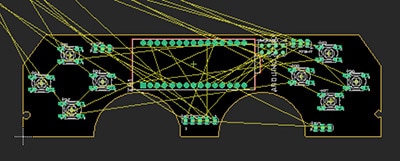
Moving on to the board layout, the first thing I did was place the microcontroller in the center and fan out all its signals. Trust me, trying to route a bunch of signals at the end of the design is a recipe for frustration. Next up were the magnetic connectors around the edge. This step was crucial. I had to meticulously consult the datasheet to ensure the spacing was absolutely perfect so that the tiles would snap together without any mechanical interference. Precision is key here. Next came the placement of all the passive components for the LEDs. It's important to remember that not all the tiles in this game will be identical. For this first pattern, we have one pathway running from the bottom to the top, a second arcing pathway on the left side, and its mirror image on the right. Remember those mating pairs for the connectors? Take a closer look at the layout. Connectors one, three, and five are the pin type, while two, four, and six are the pad type. This clever design means that the tiles can only connect in specific orientations. What's fascinating is how these technical constraints are actually shaping the game's design in an interesting way. I think it will lead to some really engaging gameplay.
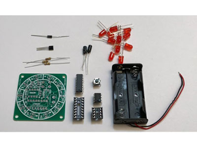
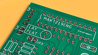
With the basic concept solidified, it was time to place an order with DigiKey for all the necessary components and PCBs. After a few days of anticipation… they arrived! Seriously, no matter how many times I order PCBs, that unboxing feeling never gets old. They just look awesome. Of course, the first thing I did was scrutinize the boards, and naturally, I spotted a couple of things I'd tweak in the next revision. I wouldn't necessarily call them mistakes, just areas for improvement. For instance, the silkscreen markings for the light paths don't quite extend to the edge of the board. There is no technical reason for this and extending them would simply make the paths a little clearer visually. A minor change for revision two. The more significant issue was the footprint for the magnetic connectors. When I insert a connector, there's a tiny bit of wiggle room. For many designs, a little play in a connector isn't a significant issue, but for this project, where precise alignment is crucial for the tiles to fit together seamlessly, even a slight misalignment during soldering could introduce noticeable gaps between the PCBs. For future iterations, I will be adjusting the footprint to be much tighter, ensuring a snug fit for the connectors. Aside from those two minor issues, these boards look fantastic, and I'm itching to start soldering on all the components I ordered.
Before I proceeded with the assembly, I wanted to conduct a quick sanity check to ensure the fundamental concept was even viable. I soldered on the microcontroller, a few capacitors, and two LEDs. That should be enough to program the chip and hopefully light up those LEDs. So, I hopped on the computer and connected my UPDI programmer. This was actually a new interface for me – my first time programming a microcontroller using UPDI. After some digging, I found the board support package and an example library for the microcontroller. I had a simple goal to blink two of the NeoPixel LEDs. I tweaked the pin number and the number of pixels in the code, and then I uploaded the code. It failed. Upload error. Exit status one. The classic engineering experience. Good thing I wasn't expecting it to work flawlessly from the start. Time to put on my detective hat, dive into the datasheets, and figure out what went wrong. After poring over the documentation for both the programmer and the microcontroller, I realized I had missed a couple of crucial settings in the Arduino menu. I also double-checked all the solder joints on the microcontroller to ensure a solid connection. Fingers crossed; this should do the trick. And… upload! Boom! It looks like the code has been successfully uploaded. Flipping the board over, you can see the simple LED animation I wrote is working perfectly. It's blinking one LED on each branch in a different color – red, green, and blue. I’m glad that wasn't a significant hurdle. This gives me the confidence to move forward and start assembling more of these tiles.
I went ahead and assembled two more boards, soldering all the LEDs onto them. Now for the moment of truth. Will these tiles actually work together? I rigged up a small magnetic connector powered by a USB-C cable. Plugging it into the edge of the first tile… It lights up! Now, let's see what happens when I snap the second tile into place. Look at that! The path of light continues seamlessly onto the second tile! And finally, let's connect the third tile. If you look closely, the light path continues and returns to the starting tile, completing the circuit. I was hoping to see that final connection light up, and it did!
As exciting as this is, this is just the first step. My goal for this video was to prove that I could create two or more tiles that magnetically snap together and react electronically based on their connection, and I've definitely achieved that! Now comes the really exciting and fun part: building this out into a full-fledged board game. In the next video, I'll flesh out the gameplay mechanics, design different tile patterns, and bring this whole idea to life with lots of colors and exciting interactions. So, make sure you don't miss part two of this board game build!