Why a Good LNA is Key to a Viable Antenna Front-End
One of the first lessons about RF and wireless links that any student learns is that antennas adhere to the reciprocity principle. This means that the transmit and receive characteristics of an antenna are identical, with no difference in attributes such as transmit or receive gain, beamwidth, or radiation patterns between the two modes. If you know the specifications of the antenna in transmit mode, then you also know them in the receive mode. Of course, antennas for higher power transmission are often made of physically larger elements as needed to handle the power, but reciprocity still holds.
There is some research into non-reciprocal antennas using metasurfaces and metalenses, but they are in the R&D stage and not a concern here.
Reciprocity is certainly a simplifying design principle, but there is much more to transmit and receive-side antenna paths than the antenna. The transmit side has a fairly easy task as it is a deterministic function: it takes a known, relatively strong signal with defined attributes, which has passed through the power amplifier (PA), and “presents” it to the antenna. There are few unknowns in the path except the detailed content of the signal modulating the carrier, and that is largely (but not entirely) of very little concern to the antenna.
In contrast, the receiver signal path operates in a much more difficult, random-like scenario. It must somehow locate and capture a tiny amount of RF signal power, and act as an electromagnetic (EM) field transducer to convert that power into a usable voltage. It must do this despite in-band noise and interference of various types and sources, as well some transmitter drift, and even Doppler-induced frequency shifts in some applications.
This received power is quite low, on the order of milliwatts (mW) in a few cases and microwatts (µW) in most, so the corresponding voltage created at the antenna is usually on the order of microvolts. The voltage is too small to be used directly for demodulation in most cases, so the answer is obvious: just amplify it. To get some perspective, the received signal power for GPS signals is typically between -127 and -25 decibels (dB) relative to one milliwatt (dBm), and viable Wi-Fi signals range between -50 dBm and -75 dBm.
Low SNR is the complementary problem
The amplification solution answer tells only part of the receiver story. It’s not hard to amplify even a microvolt signal by several orders of magnitude. However, the original signal also has noise, and what really affects the ability to demodulate and decode the received signal is its signal-to-noise ratio (SNR). Any amplification of the received signal will also amplify the embedded noise. Using a larger antenna with higher passive gain will increase the received signal power, but the received SNR will be unchanged.
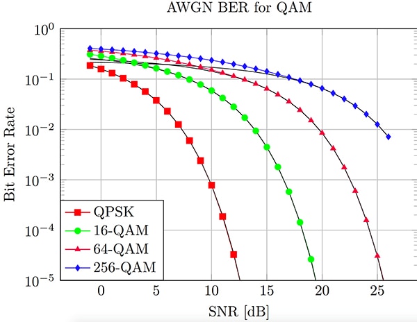
One of the key metrics of system performance is its bit error rate (BER) versus SNR (Figure 1). The specifics of those curves depend on many factors including received signal strength, SNR, and what type of error-correction code (ECC) encoding of the raw data is used at the transmitter; for this reason, the more-detailed graphs show the BER vs SNR for the raw, uncorrected bits stream as well as the corrected bit pattern (QAM = quadrature amplitude modulation).
 Figure 1: The standard plot of BER versus SNR reveals a great deal about system performance; note that more advanced modulation techniques such as 256-QAM can increase the effective data rate, but at a penalty in BER at a given SNR. (Image source: Julia Computing, Inc.)
What are some typical SNR values which result in successful demodulation with acceptably low BER? There is no universal answer, of course, but an acceptable Wi-Fi signal SNR is 20 to 40 dB, 40 to 50 dB for an old-fashioned all-analog TV, and about the same for cellular links.
There are extreme examples, of course: signals are still being received from the Voyager 1 and Voyager 2 spacecraft, both launched in 1977 and now over 11 billion miles from Earth. These signals arrive here from their 23 watt transmitters with signal power of less than an attowatt (a billionth of a billionth of a watt) and an SNR of only a few dB. To compensate for this to some extent, their data rate is now throttled down to around 100 bits/second (bits/s), down from the several kilobits/second (Kbits/s) rate when much closer with much higher received signal strength.
LNAs to the rescue
There’s an engineering cliché that originated in the early days of “wireless” and is still true: if it wasn’t for noise, the challenges of most system designs would be much, much easier. This is true of a receiver’s antenna link for a simple reason. The amplifier, which is needed to “gain-up” the weak received signal, contributes its own noise to that signal, as does any interconnection cabling between antenna and receiver front-end.
The need to amplify the received signal presents a dilemma. On one side, the unamplified signal is too weak to be useful; on the other hand, amplification increases the signal magnitude, but also degrades SNR and thus potential link performance. This dilemma is resolved to a large extent by choosing an amplifier that contributes as little noise as possible.
The front-end low-noise amplifier (LNA) has two parameters of primary interest: how much noise it adds to the signal, and how much gain it can provide. LNAs fabricated with highly specialized analog processors do one thing well (provide gain with little added noise of their own) and are not suitable for non-LNA applications.
One example is Skyworks Solutions’ SKY67180-306LF, a two-stage, high-gain LNA for 1.5 to 3.8 gigahertz (GHz) applications such as cellular repeaters and small/macro-cell sites for LTE, GSM, and WCDMA applications, as well as S-band and C band ultra-low-noise receivers (Figure 2).
 Figure 2: The Skyworks Solutions SKY67180-306LF is a two-stage, 31 dB gain LNA for 1.5 to 3.8 GHz with 0.8 dB NF; the first stage is optimized for low noise figure while the second stage provides additional gain. (Image source: Skyworks Solutions)
The first stage of this 16-lead QFN device uses GaAs pHEMT transistors for an ultra-low noise figure (NF), while the output stage (heterojunction bipolar transistors) provides additional gain at that frequency, along with high linearity and efficiency. The result is an LNA with a noise floor (NF) of 0.8 dB and 31 dB gain at 3.5 GHz.
Another critical issue is where to physically place the LNA; it’s obviously easier to put it with the rest of the receiver circuitry. However, this means that the unavoidable thermal noise of the cable carrying the amplified signal from the LNA to the system will be added to the unamplified signal, further reducing SNR. For this reason, even consumer applications such as very small aperture terminal (VSAT) satellite dishes put the LNA right at the focal point of the dish.
Conclusion
Although antenna transmitter and receiver functions adhere to the principle of reciprocity, their actual challenges diverge. For many RF antenna situations, a dedicated LNA is often the best or only way to boost the received signal level to a usable value while having minimal impact on SNR. Specialized LNAs are available that are tailored to specific frequency bands and with gain values that can resolve the signal level/SNR dilemma.
Related Content
“Get the Most Out of Exotic Processes for 5G LNAs”
https://www.digikey.com/en/articles/get-the-most-out-of-exotic-processes-for-5g-lnas
“Understanding the Basics of Low-Noise and Power Amplifiers in Wireless Designs”
“Low-Noise Amplifiers Maximize Receiver Sensitivity”
https://www.digikey.com/en/articles/low-noise-amplifiers-maximize-receiver-sensitivity
References
- Increase Broadband Speed, “Wi-Fi Setup Guide: What is a Good Signal Level or Signal-to-Noise Ratio (SNR) for Wi-Fi?”
- Nordic Semiconductor, “GPS functionality test”
- The Great Courses Daily, “Voyager 2” Sends Messages from Interstellar Space with Minimal Signal”
- National Radio Astronomy Observatory, “How Strong is the Signal from the Voyager 1 Spacecraft When it Reaches Earth?”
- IEEE Communications Society, “Voyager - A Space Exploration Mission Like No Other”

Have questions or comments? Continue the conversation on TechForum, DigiKey's online community and technical resource.
Visit TechForum


