The Evolution of Model Railroading as Proxy for the Electronics Industry
The earliest model railroads were simple in implementation but limited in performance. Electric power was fed to the locomotives via the track rails, and the speed of the engine was controlled by varying the applied voltage (typically up to 18 volts DC). Engine performance was marginal at lower speeds since the torque versus voltage curve for DC motors is poor at reduced voltage, and so engines and trains would have a stop-and-go stutter instead of crawling slowly.
If a motor specifically designed for lower voltage operation was used instead to compensate for this shortcoming, it then lacked the power needed to pull more than a few cars. It was all basic DC loops and there were no electronics, but some advanced hobbyists employed mechanically tripped contact-closure switches on the model layout for activating signals, controlling lights, and creating other realistic actions.
As solid state devices became available, electronics soon solved the low-speed motor control problem using pulsed power. Instead of using simple lower voltage DC for low speeds, the full voltage (or nearly so) was applied using pulse width modulation (PWM). Thus, the motor functioned well at low speeds and provided nearly full torque, but now motor chatter and vibration became new issues. Vendors of these PWM DC power packs addressed this problem with various adaptive schemes which shaped and shifted the PWM waveform depending on the throttle setting.
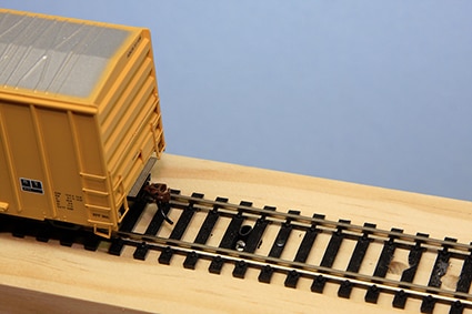 Figure 1: An upward-facing photocell placed between the tracks is the core of a simple track occupancy detector, but it also has some undesirable operating characteristics. (Image source: Iowa Scaled Engineering, LLC)
Along with the use of electronics by vendors in the power pack, model railroad enthusiasts (hobbyists) also began using transistors and electro-optical components on the layout. One such example was occupancy detection, which was used to determine if a section of track was in use. This enabled semi-automatic train control as well as other functions. Several optical detection techniques were commonly used, each with tradeoffs in complexity, performance, and cost.
The simplest technique uses optical sensors, and there are many variations of this approach. In the basic version, a photocell was buried between the tracks (Figure 1). If the photocell is blocked by any car, its output drop is sensed by a simple comparator circuit. While this is fairly straightforward, the comparator trip point must be tuned to the ambient light intensity, and variations from people moving around and other layout activity can cause false triggering.
A better but more complicated method uses an infrared (IR) LED rather than ambient light and a complementary phototransistor. In transmission mode designs, the pair is placed on opposite sides of the track with the light path blocked by any car; in the physically simpler reflective mode implementation, the pair are placed in a single housing, but dark cars may not reflect enough light back to the phototransistor. As usual, it’s the tradeoff of simplicity versus consistency and ease of execution. Advanced designs even modulate the LED drive so there is no confusion due to ambient light.
Other occupancy detection schemes do not use optics at all, but instead use current sensing. In this method, a kilohm range “bleeder” resistor is attached between the two normally insulated wheels of the car’s truck (wheelsets are insulated from each other at their axles to prevent shorting out the track rails). A current sense transformer and some electronics sense the flow through the resistor leakage path, indicating a car on the tracks. Note that this approach requires that the overall layout track must be electrically divided into isolated blocks so you know where the detected car actually is, beyond the fact that there is a car on the tracks.
A representative schematic of a dual-channel current sense block occupancy detector shows the sophistication of the circuit (Figure 2). The critical transducer is a transformer such as the Pulse Electronics FIS121NL 1:200 current sense transformer used for T1 and T2, with its center hole to provide a path for the wire carrying the current being sensed.
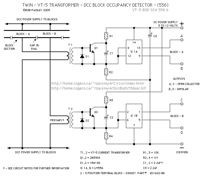 Figure 2: The current flow approach depends on a trickle of current flowing across the tracks through a wheelset bleeder resistor. The current is sensed by a current transformer with a center hole. (Image source: Circuitous.ca)
This method has its own drawbacks: every car to be sensed needs the added bleeder resistor, and the optimum value for the bleeder is a compromise between sensitivity and false tripping, the length of track, and the associated IR drop, among other factors.
Going beyond simple DC: get networked
As the many add-on circuits grew in number and sophistication, their cost, complexity, incompatibility, and maintenance issues reached an unsustainable level. Further, there is an unavoidable issue when directly powering motors from the track rails: every engine sees the same voltage, so they are not individually controllable.
The only practical DC-based solution is to physically divide the track into electrically isolated blocks and use multiple power packs, with one per engine. As the given locomotive moves from one block to the next, the layout operator has to switch its controlling power pack as well. When there are more than two or three locomotives operating at the same time, management becomes frustrating, and tiring; there are some semi-automated schemes, but these are inflexible, complicated, and costly.
Fortunately, ICs and on-chip power control (MOSFETs) offered a way out. In the mid-1990s, the National Model Railroad Association (NMRA) and industry vendors established an open standard called Digital Command Control (DCC) which took model railroading into the networked world. With DCC, full power is always provided to the track, and each locomotive is assigned an ID as a network node. Coded signals are sent on the track indicating how much power should be delivered to the motor at that ID via an embedded motor control IC with about 1 ampere (A) capacity. DCC caught on quickly since it solved a genuine set of problems and worked across all vendors, much like Wi-Fi. The locomotives were network nodes, with each given its instructions via the rails functioning as a data bus.
Soon, the DCC role expanded well beyond locomotive speed control. Sound effects were programmed into ICs mounted on board, along with tiny speakers, all controlled by DCC commands. There are also DCC-compatible motors for setting the track turnouts (also called switches) and other non-motive functions, all made possible by specialized DCC decoder ICs and unique node IDs. DCC is now used in the vast majority of layouts, and it has matured to be almost a “plug-and-play” system. It also allows operation of the layout via a PC or even a smartphone, with pre-set operational scenarios and automated switching sequences.
Power interruption still an issue
Like most networks, DCC has one major weakness: it doesn’t work when power is cut off. There can be a brief but crippling of loss of DC power to the decoder and thus the motor due to a variety of reasons: track gaps which isolate track operating blocks; gaps where polarity must be switched “on the fly” due to reverse loops where the rails cross over themselves (Figure 3); gaps in the track physical continuity at the “frog” of a turnout; and intermittent contact between the wheels and the track. At slow speeds, there may not even be enough momentum to coast through the gap, and manual intervention (a push) may even be needed.
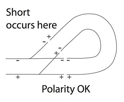 Figure 3: The reverse loop is an unavoidable aspect of using the two track rails for power delivery and occurs when the track loops back on itself; the loop must be isolated and the main track’s power polarity reversed by a DPDT switch while the train is in the loop. (Image source: The Spruce Crafts)
Once again, modern components offer a solution to the problem. By wiring a few supercapacitors in series to provide about 20 to 25 volts output and placing the package on-board, they provide “keep-alive” (also called “stay-alive”) power through the “dead zone” period. The supercapacitors are continuously charged via the rails, providing a simple yet effective solution (Figure 4). A viable choice for the supercapacitor is the Kemet FM0H103ZF, a 10 millifarad (mF), 5.5 volt unit; using five in series ensures enough DC voltage and carry-through energy to support a typical HO (1:87) scale locomotive for one to two seconds.
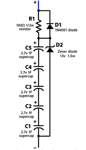 Figure 4: Typically, a series string of supercapacitors placed in parallel with the motor control IC power connections can provide backup power for the engine as it traverses a gap in the power rails. Actual capacitance values may vary based upon desired backup run time. (Image source: Model Railroader Hobbyist Magazine)
There is one problem with this solution: there’s usually no room for even small supercapacitors in model diesel locomotives in small-to-midsize scales such as O (1:48), and certainly no room at smaller scales of HO (1:48), S (1:64), N (1:160), TT (1:120), or Z (1:220). However, old-fashioned steam locomotive models can use these supercapacitor “keep alive” packs since they have their attached tender (for wood or coal in real life) which provides a location for them.
Next: power without tracks
It is easy to assume that delivering power to the locomotives is simple. After all, there are those two very tangible track rails which can also be used as power rails, as well as encoded data in a DCC system. However, the reality is that reliably delivering power via those rails is often an ongoing problem due to the reasons cited previously.
Once again, improvements in basic electrical components are enabling innovative alternatives. Instead of drawing power from those track rails, what if you could carry the needed power on-board via rechargeable batteries? Suddenly, all of the many problems associated with using tracks for power delivery disappear. There are some modelers who have done this at the larger model scales such as G (1:24), which is often used for outside “garden” layouts; that’s an environment where rail-based power paths are especially troublesome due to rust, corrosion, leaves, grass, and other obstacles.
So how do you control the engines if there is no wired track connection? Use a short-range wireless-link module which embeds a DCC decoder with an RF front-end in place of the rail-based DCC path. All the needed modules are available as standard, off-the-shelf items from specialty suppliers, and a typical installation has a run time of 20 to 30 minutes.
As batteries improve, onboard power may become viable for the very popular smaller scales. This would truly be a paradigm shift in model railroading as dramatic as DCC has been. It’s not just electric vehicles (EVs) that will benefit from increased battery energy density. As we have seen many times, advances in a well-defined target area often enable benefits in unrelated applications.
References and further reading:
1: National Model Railway Association, “Beginners guide to Command Control and DCC”; https://www.nmra.org/beginners-guide-command-control-and-dcc
2: Wikipedia, “DCC Tutorial (Basic System)”; https://dccwiki.com/DCC_Tutorial_(Basic_System)
3: Wikipedia, “Digital Command Control”; https://en.wikipedia.org/wiki/Digital_Command_Control
4: Azatrax, “Model Railroad Infrared Train Detection”; http://www.azatrax.com/ir-model-train-detector.html
5: Circuitous.ca, “Block Occupancy Detector For DCC”; http://www.circuitous.ca/DccBODvt5.html
6: Model Railroader Hobbyist Magazine, “Build an optical detector circuit”; https://model-railroad-hobbyist.com/node/23535
7: Kalmbach Media, “Model Railroader”; https://mrr.trains.com/
8: Iowa Scaled Engineering, LLC, “2018 Optical Detector Roundup”; https://www.iascaled.com/blog/2018-optical-detector-roundup/
9: Model Railroader, “Keep Alive Circuit For Passenger Car Lighting” ; http://cs.trains.com/mrr/f/744/p/268873/3047228.aspx
10: Model Railroad Hobbyist Magazine, “Build your own stay alive” ; https://model-railroad-hobbyist.com/magazine/mrh2019-06/electrical-impulses
11: The Spruce Crafts, “How to Build and Wire Reverse Loops for Model Trains” ; https://www.thesprucecrafts.com/reverse-loops-model-trains-2382604

Have questions or comments? Continue the conversation on TechForum, DigiKey's online community and technical resource.
Visit TechForum


