The Doppler Effect: Now Widely Accepted and Easy to Use, Despite Its Initial Rejection
Engineers are familiar with many “effects” ranging from widely used ones such as the piezoelectric effect, to somewhat lesser-known ones such as the RF skin effect, and even less familiar ones such as the Coanda effect, to cite just a few. But there’s one effect that is both widely known and widely used by engineers in systems across many disciplines: the Doppler effect. Named after physicist Christian Doppler, who described the phenomenon in a theoretical paper in 1842, the Doppler effect is the change in frequency of a periodic wave with respect to an observer who is moving relative to the wave source (one or both may be moving).
By employing the Doppler effect and its associated Doppler shift, it is possible to determine the relative motion (both speed and acceleration) of a sensed object as perceived by the observer. It is a versatile and vital phenomenon of wave physics that has a long list of applications from very small scale to extraordinarily large scale, including:
- Ultrasonic Doppler to sense blood flow in the circulatory system.
- Ultrasonic and RF Doppler to sense the motion of people in an area.
- Optical Doppler to determine an autonomous vehicle’s speed.
- RF Doppler in radar to determine the movement of vehicles, ships, aircraft, and even spacecraft.
- Optical and RF Doppler combined to measure the speed of spacecraft, and even astronomical bodies such as stars and galaxies (often referred to as redshift for those receding and blueshift for those approaching).
In recent years, technological advances have used the Doppler effect as an enhancement for many sensing systems. For example, early medical ultrasound systems could show the presence and size of veins and arteries, while adding the Doppler aspect allows for measurement of the speed of blood flow, a major diagnostic improvement.
The Doppler principle
Although it can be defined with precise equations, the Doppler effect can also be described conceptually. When the source of repetitive waves at constant frequency is moving towards the observer, each successive crest of the wave series begins at a position that is slightly closer to the observer than the crest of the previous wave. Thus, each successive wave takes slightly less time to reach the observer than the previous one; this, in turn, has the effect of shrinking the arrival time between successive wave crests at the observer, corresponding to an increase in the observed frequency (Figure 1).
 Figure 1: As the source and observer move closer, the distance between successive wave crests decreases, resulting in a rise in perceived frequency; the opposite is the case as the two move apart. (Image source: Science Facts)
If the opposite occurs, with the source of waves moving away from the observer, then each subsequent wave is sourced from a position further from the observer than the previous wave, thus stretching the spacing between crests. Since the arrival time between successive waves is increased, and these crests spread apart, the frequency as determined by the observer is reduced.
You’ve doubtlessly heard and become used to the Doppler effect when a car which is blowing its horn or siren approaches and then passes you (Figure 2). The perceived frequency rises as the car approaches (as does the intensity, of course), then suddenly drops as it passes (again, along with the intensity); railroad horns also have the same easily heard and dramatic effect.
 Figure 2: As the vehicle approaches at a constant velocity, the observer hears a steady higher pitch (top graph) even as the intensity gradually increases (lower graph); as the vehicle passes, the pitch suddenly drops while the intensity fades. (Image source: ResearchGate)
While the designation Doppler effect is widely used, there are really two different physics “mechanisms” at play and two sets of descriptive equations. One for acoustic waves and the other for electromagnetic ones. Why the difference? For acoustic energy and other energy waves that propagate in a tangible medium (air, water, even solids), the velocity of the observer and the velocity of the source are measured relative to the medium in which the wave energy is transmitted. That seems pretty clear, and the overall observed Doppler effect is the result of the motion of the source alone, the observer alone, both source and observer, and even the motion of the medium.
However, for electromagnetic energy (light, RF) which does not require a tangible medium such as air, the Doppler analysis is somewhat different, and only the relative difference in velocity between the observer and the source enters into the analysis. This is associated with a premise of special relativity, where one of Albert Einstein’s radical postulates in his 1905 paper was that the speed of light with respect to any inertial frame is a constant, and is independent of the motion of the light source itself.
Note that in many systems, the frequency source and observer are co-located, and the Doppler effect is seen as a reflection from a target; this adds a factor of two into the relevant equations, but the principle is otherwise unchanged.
Doppler, back in the day
The explanation of the Doppler effect is almost intuitive to us, with our understanding of wave phenomena along with available frequency sources and measurement equipment. Doppler described the phenomenon as an explanation for how the color of the starlight changed with the movement of the star. However, there was no means available at the time to properly test his assertion. In fact, he was ridiculed by many other prominent physicists and even expelled from a leading scientific association due to his “heretical” ideas. It took several decades, along with the inability of researchers to resolve inconsistencies of data recorded from various experiments that had not been corrected for his eponymous effect, to win over his detractors.
An unrelated advance helped his case: the development of the railroad in that era, which allowed repeated tests to be run using linear motion and along a track at a fixed-speed sound (a band was even used on one train!), which helped confirm his assertions. The story of Doppler’s trials and tribulations is told in a detailed, annotated article in a recent issue of Physics Today (see References). It’s a lesson worth remembering: ideas that are ridiculed at first may eventually be accepted as “correct” (think of Galileo and his solar-centric view of our system). Christian Doppler was ultimately vindicated, as his name is now the standard designation for his initially rejected analysis and conclusions.
While the Doppler effect is a very useful phenomenon, it is also a source of many engineering challenges. How so? While it can be used for measuring velocity, it also affects frequency stability. For example, the nominal carrier frequency of Earth-orbit satellites (such as GPS) and deep-space vehicles (such as the recent Mars lander) shifts due to the Doppler effect. So the transmit and receive paths must compensate and accommodate these frequency shifts, which can be substantial given the velocities of these vehicles.
Doppler gets smaller
Though it’s complex, the Doppler effect is so useful, that many circuits and systems make use of it as a primary or secondary function. To allow this, vendors have worked tirelessly to make devices that use the Doppler effect easier to embed by developing smaller packages at lower power and with advanced development tools and boards to expand its use.
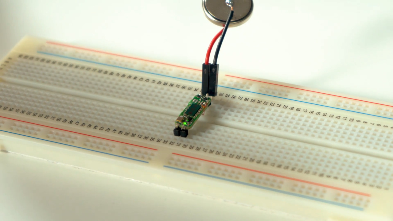
A recent example is the Infineon Technologies DEMOBGT60LTR11AIPTOBO1 evaluation board. This unit is designed to replace the widely used passive infrared (PIR) motion detector by offering better performance, response, and user programmability, utilizing 60 gigahertz (GHz) Doppler-effect technology.
 Figure 3: The Infineon Technologies DEMOBGT60LTR11AIPTOBO1 evaluation board provides a 60 GHz Doppler-based motion sensor that is superior to the PIR approach. (Image source: Infineon Technologies)
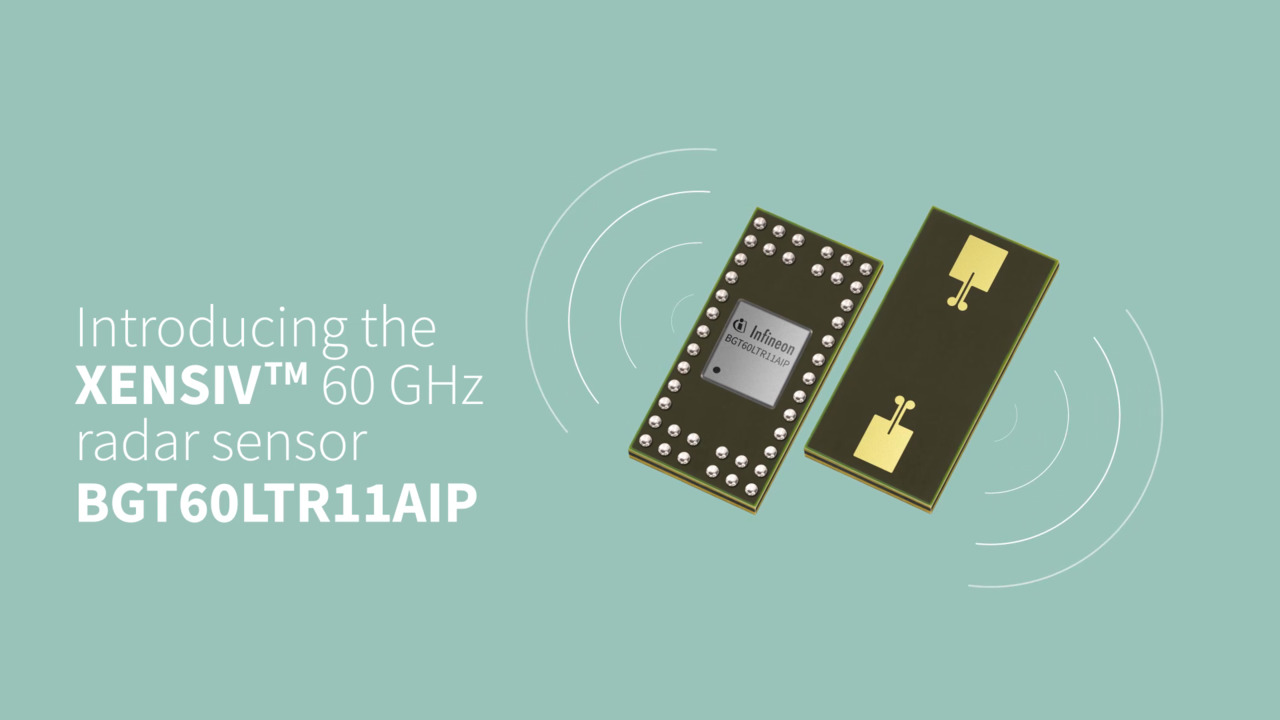
Based on the BGT60LTR11AIP fully integrated 60 GHz monolithic microwave integrated circuit (MMIC) measuring 3.3 × 6.7 × 0.56 millimeters (mm) (Figure 4), this kit provides a Doppler-based motion sensor and includes antennas in package (AIPs) with an 80˚ field of view, as well as integrated detectors for motion and direction of motion. Adjustable performance parameters include detection sensitivity, hold time, and frequency of operation, and unlike many 60 GHz devices, it uses standard, low-cost FR4 circuit board material.
 Figure 4: The block diagram of the Infineon BGT60LTR11AIP radar-based motion sensor MMIC shows its internal complexity. (Image source: Infineon Technologies)
The development kit includes the BGT60LTR11AIP “shield,” as well as the Infineon Radar Baseboard MCU7. The 20 × 6.25 mm shield demonstrates the features of the BGT60LTR11AIP MMIC and gives the user a “plug and play” radar solution. It’s optimized for fast prototyping of designs and system integration, as well as an initial evaluation of features and functions.
Conclusion
Doppler effect sensing is a cornerstone of many modern systems, as it quantifies the use of electromagnetic and acoustic wave energy as a noncontact, almost instantaneous means of determining the motion of objects at a distance. It is used in a variety of settings ranging from microscopic to astronomical. Thankfully, modern components and development kits simplify the incorporation of functions based on the Doppler effect and shift, both in cases where there is no viable alternative, as well as an improved replacement for existing approaches.
References:
1 – Physics Today, “The fall and rise of the Doppler effect”
2 – NASA, “Doppler Shift”
3 –Georgia State University, “Doppler Effect”
4 – University of Connecticut, “Doppler Effect”
5 – University of Virginia, “Doppler Effect”
6 – Wikipedia, “Coanda Effect”
7 – Wikipedia, “Skin Effect”
About this author

Bill Schweber is an electronics engineer who has written three textbooks on electronic communications systems, as well as hundreds of technical articles, opinion columns, and product features. In past roles, he worked as a technical web-site manager for multiple topic-specific sites for EE Times, as well as both the Executive Editor and Analog Editor at EDN.
At Analog Devices, Inc. (a leading vendor of analog and mixed-signal ICs), Bill was in marketing communications (public relations); as a result, he has been on both sides of the technical PR function, presenting company products, stories, and messages to the media and also as the recipient of these.
Prior to the MarCom role at Analog, Bill was associate editor of their respected technical journal, and also worked in their product marketing and applications engineering groups. Before those roles, Bill was at Instron Corp., doing hands-on analog- and power-circuit design and systems integration for materials-testing machine controls.
He has an MSEE (Univ. of Mass) and BSEE (Columbia Univ.), is a Registered Professional Engineer, and holds an Advanced Class amateur radio license. Bill has also planned, written, and presented on-line courses on a variety of engineering topics, including MOSFET basics, ADC selection, and driving LEDs.

Have questions or comments? Continue the conversation on TechForum, DigiKey's online community and technical resource.
Visit TechForumRelated Blogs


More Blogs from this Author