How to Implement High-Performance Modular Connectivity for Enterprise Data Center Equipment
When designing servers, storage, and networking equipment to support big data applications in enterprise and cloud data centers and next-generation communications infrastructure, you can be challenged to provide compact connectivity solutions to accommodate the necessary data rates. These rates include high-speed signals up to 56 gigabits per second (Gbps) using four-level pulse amplitude modulation (PAM4), Peripheral Component Interconnect Express (PCIe) generations 4 and 5, non-volatile memory express (NVMe), serial attached SCSI (SAS), small form factor pluggable (SFP), and quad SFP (QSFP) specifications.
The applications in question demand slim, cost-effective connectors that provide high levels of signal integrity (SI), modularity, and scalability, and that minimize downtime through ease of maintenance and repair. They also need connectors that can deliver multiple mating cycles with low insertion forces, and impedances such as 92, 85, and 95 ohms (Ω) to support various interoperability and SI needs.
This blog introduces and briefly describes the industry standards and SI needs of PAM4, PCIe, NVMe, SAS, SFP, and QSFP. It then uses PCIe as an exemplary application to discuss the importance of impedance selection and the need for slim card edge and cable connector solutions in high-density servers, storage, and networking equipment. Along the way, we’ll look at some Mini Cool Edge connector options from Amphenol that you can use for high-performance, compact, modular connectivity in enterprise and cloud data center equipment.
Meeting standards & achieving SI
The Mini Cool Edge connector specification meets the Storage Networking Industry Association (SNIA) small form factor (SFF) TA1002 standard that includes right angle, straddle mount, and orthogonal connectors for servers and storage devices. This standard has been adopted by Enterprise and Datacenter Standard Form Factor (EDSFF) and Open Compute Project (OCP) committees for solid state-drive (SDD) and network interface card (NIC) 3.0 applications, respectively.
Mini Cool Edge 0.60 millimeter (mm) IO OverPassTM solutions (specifically designed for flyover applications) also support low latency Gen Z system architectures, which deliver high performance and enhanced SI. These connectors feature highly stable and balanced impedances, and S parameters like insertion loss, return loss, and cross-talk that enable the SI needed for high-speed connectivity. They support both add-in card (AIC) and cabled applications, up to 56 Gbps PAM4, PCIe Gen 4 and Gen 5, over a 1 meter (m) transmission distance. Impedance options include 85 Ω (G97 series), 92 Ω (G42 series), and 95 Ω (G98 series). Various pin counts are available meeting PCIe, NVMe, SAS, SFP(+), and QSFP specifications.
As mentioned earlier, the Mini Cool Edge connectors support many interface specifications. However, the rest of this blog will discuss the design considerations required for a PCIe interface.
What impedance do you need?
There are many factors to consider when designing high-speed interconnects for PCIe interfaces—including printed circuit (pc board) traces and vias—and connectors are near the top of the list. Maintaining SI when designing compact modular connectivity solutions is critical, and selecting the correct impedance is essential to achieving this.
Complicating the determination of the optimal impedance are the many types of PCIe interconnects. Examples include midplane-to-motherboard (MB) flyovers, chip-to-chip flyovers, chip-to-external input/output (I/O), and others (Figure 1). These interconnects can have an IC package at one or both ends and can include multiple pc boards like a processor board, riser, or add-in cards. And there are PCIe card electromechanical (CEM) connections. The requirement for an 85 Ω impedance ensures the interoperability of systems and cards using the CEM specification, guaranteeing matched impedances for any mated devices. However, 85 Ω is not an absolute requirement of PCIe.
 Figure 1: Flyover interconnects take a variety of forms and need to support high SI. (Image source: Amphenol)
What if CEM interoperability is not required?
CEM interoperability is not mandatory for many PCIe applications. The PCIe specification states that the 85 Ω requirement doesn’t necessarily apply to connectors, cables, vias, and other interconnects. It’s just needed for CEM interoperability. Without the need for interoperability, the choice of interconnect impedance depends on your SI priorities. For example, if insertion loss is the priority, higher impedances like 92 or 95 Ω can be a better choice.
In addition to needing a range of impedance choices to optimize SI, you need a variety of physical connector configurations that can support various mechanical designs like left and right side exits, as well as right-angle (RA) and straight interconnects (Figure 2). Compared with pc board traces, the correct flyover connector and cable solution can enable longer interconnect lengths with high SI, and support modularity and expandability while simplifying maintenance and repair.
 Figure 2: Connectors with a variety of physical configurations can support the packaging needs of specific applications. (Image source: Amphenol)
Compact PCIe connectors
When you’re designing PCIe interconnects, you can turn to the Mini Cool Edge IO OverPassTM connectors from Amphenol. These slim connectors provide you with a new approach to system design that is modular, scalable, easy to repair, and cost-effective. Along with a 0.60 mm pitch and support for high-speed signals up to 56 Gbps PAM4/PCIe, Gen 4/PCIe, and Gen 5/PCIe, other key features include:
- Vertical and right-angle configurations (Figure 3).
- Straight, right-angle, and left and right side cable exits.
- Support for up to 56 Gbps signals—over a 1.0 m transmission distance.
- The same connector can support cable and card edge designs.
- Several impedance choices include 92 Ω (the G42 series, like the 74-position G42V12312HR), 85 Ω (the G97 series, like the 148-position G97R26312HR), and 95 Ω (the G98 series, like the 38-position G98V11312HR).
- The ability to withstand 250 mating cycles, with a mating force of 0.6 Newton (N) per pin, maximum, and an unmating force of 0.06 N per pin, minimum.
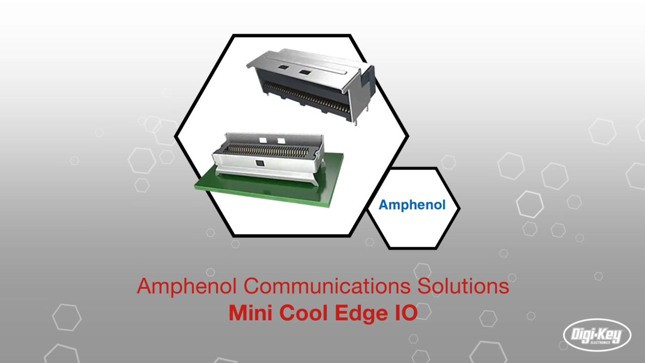
 Figure 3: Vertical (bottom) and right angle (top) Mini Cool Edge IO connectors have a 0.60 mm pitch. (Image source: Amphenol)
Conclusion
When designing PCIe interconnects for enterprise data center equipment like servers, storage, and networking equipment, you don’t have to look much further than Amphenol’s Mini Cool Edge IO OverPassTM lineup. It provides the range of connector options that meet a variety of industry standards and support your SI need, while also providing cost-effective solutions for modular, scalable, and easy-to-repair configurations.

Have questions or comments? Continue the conversation on TechForum, DigiKey's online community and technical resource.
Visit TechForumRelated Blogs


More Blogs from this Author
 Custom PCB Orders")