A Single IC Solves the Single-Phase Energy-Metering Challenge
These days, discussions related to “energy” and “power” are ubiquitous. It’s not only at the “micro” level related to how much a circuit or system uses, but there are also considerations related to AC-line energy and power, primarily with respect to energy use, power saving, and renewable sources. Let’s look at what these terms actually mean and how to go about measuring them effectively.
One of the first lessons engineering students learn is what is meant by “energy” and “power.” These two items are related but distinctly different, yet they are often used interchangeably in casual conversation and reporting (even among engineers!)
Formally, energy is the ability to do work, and power is the rate at which energy is expended or acquired. Mathematically, power is the time derivative of energy, while energy is the time integral of power.
The root-mean-square (RMS) voltage and current value are essential in power and energy analysis. Mathematically, the RMS value of a time-varying voltage f(t) is calculated using:
 Equation 1
Where T = the waveform period.
Note that for a basic undistorted sine wave, there is a simple relationship between the peak AC voltage and RMS value:
 Equation 2
What is the meaning of RMS value in the general case? The RMS value of an AC signal compares the heating value of an unknown AC signal to that of a known DC signal across identical loads and is equal to the amount of DC required to produce the same amount of heat in the load. When the power dissipated in the loads is equal, the known DC voltage equals the RMS value of the unknown AC signal.
For example, if 1 volt AC RMS is applied to a resistive heating element, it would produce the same amount of heat produced by 1 volt DC. In fact, some pre-electronic RMS DC instrumentation used an arrangement where a DC source and the unknown RMS source heated identical resistors. The DC source was then adjusted so the resistor temperatures matched; that would indicate the RMS value.
Fortunately, ICs made the challenge of determining RMS value fairly straightforward using all-analog computation configurations (Figure 1). In this circuit, the Analog Devices AD628 programmable-gain difference amplifier (here configured for an attenuation factor of 25) scales the power-line signal down before applying it to Analog Devices’ AD8436 RMS-to-DC converter.
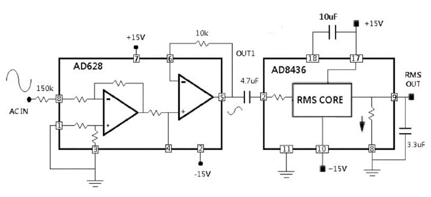 Figure 1 : This two IC, all-analog circuit provides a DC output representing the RMS input of the AC power line. (Image source: Analog Devices)
The difference amplifier has a ±120 volt common-mode input and differential-mode range, making it a good fit for dividing down the high-voltage power line. The precise DC equivalent of the RMS value of the AC waveform is provided at RMS OUT.
Today’s AC-line reality calls for much more
While the all-analog RMS-DC approach works, it can only tell you one thing. In today’s energy management environment, the system needs to know much more about the single-phase AC waveform in addition to its RMS value.
Complicating the issue is the fact that the AC voltage is not a nice, clean sine wave, but has many deviations from nominal as well as distortions. Further, the load is rarely a pure resistance, so there are phase shifts between the voltage waveform and the current waveform. Overall, there are attributes that can only be determined with additional digitally driven numerical analysis.
This AC-line reality is where Analog Devices’ ADE9153A energy metering IC with Autocalibration excels (Figure 2). It targets applications such as single-phase energy meters, energy and power measurement, street lighting, smart power distribution systems, and machine health monitoring. The ADE9153A’s 10 megahertz (MHz) high-speed serial peripheral interface (SPI) port allows access to the ADE9153A registers. It operates from a 3.3 volt supply and is available in a 32-lead LFCSP package.
 Figure 2 : The ADE9153A energy metering IC with autocalibration targets single-phase applications and has internal analog and digital functional blocks for detailed analysis. (Image source: Analog Devices)
The ADE9153A does much more than provide the basic function of digitizing the AC line’s voltage and current values. Its advanced metrology engine computes key energy/power-related results, and it can calculate line voltage and current, active energy (watt hour (Wh)), fundamental reactive energy (volt-ampere-reactive hour (VARh)), apparent energy, and current and voltage RMS calculations.
The ADE9153A also includes power-quality measurements such as zero-crossing detection, line-period calculation, angle measurement, dip and swell, peak and overcurrent detection, and power factor (PF) measurements. It provides this while supporting the standards defined by regulatory agencies, such as active-energy standards (IEC 62053-21; IEC 62053-22; EN50470-3; OIML R46; and ANSI C12.20) and reactive-energy standards (IEC 62053-23 and IEC 62053-24).
Performance begins with sensor channels
The actual performance achieved using the features and functionality of any advanced energy-metering device is heavily dependent on effective and credible sensor channels. The ADE9153A addresses these issues via two approaches: appropriate physical connectivity for the current and voltage sensors, and a unique calibration scheme.
The ADE9153A has two current channels. Channel A is a sophisticated datapath optimized for use with a shunt and is shown in both simplified and detailed form in Figure 3.
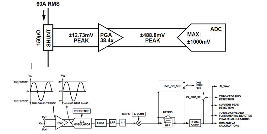 Figure 3 : Shown is the simplified application circuit with a shunt current sensor on Current Channel A (top); also shown is the detailed Current Channel A datapath (bottom). (Image source: Analog Devices)
Channel B is for use with a current transformer, also shown in simplified and detailed versions in Figure 4. Note that a digital integrator is included in Current Channel B for interfacing with a di/dt current sensor such as a Rogowski coil.
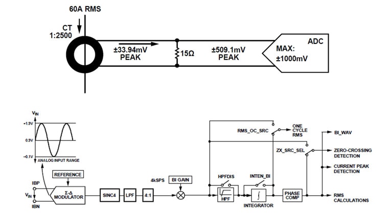 Figure 4 : Shown is an application circuit with a current transformer as a current sensor on Current Channel B (top); also shown is a detailed Current Channel B datapath (bottom). (Image source: Analog Devices)
Similarly, the ADE9153A has a single voltage channel with its own datapath, shown in simplified and detailed versions in Figure 5.
 Figure 5 : Shown is a simplified application circuit with voltage sensed through a resistor divider (top); also shown is a more detailed schematic of the Voltage Channel datapath (bottom). (Image source: Analog Devices)
For the ongoing challenge of channel calibration, the ADE9153A incorporates the mSure autocalibration feature to significantly reduce calibration time, labor, and equipment costs. This feature allows a meter to automatically calibrate the current and voltage channels without needing an accurate source or reference meter when a shunt resistor is used as a current sensor.
The conversion constant (CC) of each channel can be measured by powering up the meter. That value alone is enough to perform the auto-calibration (CC is the value that mSure returns when estimating the transfer function of the sensor and front-end). Industry-standard Class 1 and Class 2 meters are supported by mSure autocalibration. While no single number can capture the many facets of the accuracy of this IC, a good first-order working number for the results is an accuracy of about one percent.
Putting it all together
An advanced IC such as the ADE9153A is powerful and sophisticated but is not trivial to set up and use to its full potential. To address this issue, Analog Devices supports the ADE9153A with a 50-page data sheet, along with other documents that provide details on best practices for the PC board layout, as well as additional technical insight (see Related Content).
Further design-in support is offered by the EV-ADE9153ASHIELDZ Evaluation Expansion Board, which is based on the Arduino shield platform (Figure 6). The shield has an onboard shunt resistor for line-current measurement and enables quick evaluation and prototyping of energy measurement systems that use the ADE9153A.
 Figure 6: The EV-ADE9153ASHIELDZ Evaluation Expansion Board is an Arduino shield that speeds the evaluation and prototyping of energy measurement systems that use the ADE9153A. (Image source: Analog Devices)
The onboard shunt for line current measurement handles a nominal current of 5 A and a maximum current of 10 A. It supports up to 240 volt RMS (nominal) line-neutral voltage measurements.
Arduino library and application examples for the ADE9153A are also available to simplify the implementation of larger systems. Using mSure autocalibration, the shield can be calibrated to measure energy with 1% accuracy over the dynamic range without the need for expensive calibration equipment.
Conclusion
The challenges designers face in meeting today’s energy-conscious AC-line measurement requirements cannot be satisfied by a basic RMS-DC converter. Instead, they need to digitize the AC line’s voltage and current values and then apply computation functions to determine the many necessary power and energy parameters. The ADE9153A from Analog Devices provides the necessary features and accuracy to do this with its voltage and current input signal-interfacing datapaths, an internal metrology-engine core, and a standard SPI interface.
Related Content
1: AN-1562, Layout Considerations when Adding Energy Monitoring to a System Using the ADE9153A
2: UG-1253, EV-ADE9153ASHIELDZ User Guide
3: UG-1247, ADE9153A Technical Reference Manual

Have questions or comments? Continue the conversation on TechForum, DigiKey's online community and technical resource.
Visit TechForum


