Use Rugged Multiband Antennas to Solve the Mobile Connectivity Challenge
Contributed By DigiKey's North American Editors
2022-03-15
Along with smartphones and Internet of Things (IoT) devices, another major driver for mobile wireless connectivity is transportation applications, including railroads, trucks, and asset tracking. These applications put a unique set of significant demands on the system antenna such as vibration, shock, temperature extremes, rain, humidity, and the need to operate across wide bandwidths and even multiple bands, all while providing consistent performance.
While it is possible to design and build a suitable antenna, in nearly all challenging applications it makes the most sense to use a standard, properly designed, well-built, fully characterized, off-the-shelf unit. Doing so reduces cost and development time while increasing the level of confidence in the final design.
This article examines the issues associated with transportation antenna design. It then introduces two multiband antennas from TE Connectivity designed to mount on the surface of an enclosure, including a basic “box” and possibly an exposed moving vehicle.
Applications drive implementation
The antenna is the vital transducer between an electronic circuit and free-space electromagnetic (EM) fields, and so is often the most exposed element of the design. Yet it must deliver the desired electrical and RF performance despite harsh ambient conditions, using a form factor compatible with the overall system design.
For freight systems and especially high-speed passenger rail, it must also be easily integrated into an aerodynamic enclosure that both presents minimal wind resistance and can be protected from harsh environmental conditions (Figure 1). Similar constraints apply to asset tracking situations where the antenna must be exposed for receiving global navigation satellite system (GNSS) signals.
 Figure 1: Mobile connectivity using various standards and bands is now an expectation on mobile, high-speed installations such as trains, incurring challenges due to wind resistance and environmental ruggedness. (Image source: TE Connectivity)
The optimal antenna is a careful blend of application-specific characteristics, including desired radiation patterns, proper impedance match, low voltage standing wave ratio (VSWR), mechanical integrity, enclosure suitability, and ease of electrical connections. There is also the need in many cases to enhance the signal path and to maximize the front-end signal-to-noise ratio (SNR) through the use of an active antenna with an integrated low-noise amplifier (LNA).
As with all components, there are some top-tier parameters used to characterize nearly all antenna designs and installations, as well as others which may be more or less critical in a given situation. For antennas, radiation patterns and performance across the specified band are key considerations.
Implementing antenna principles
The orientation of antennas used for transportation and asset tracking is a challenge as it is random and changing, making it important for them to have a consistent, omnidirectional pattern for the top and side views throughout the specified band.
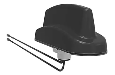
For example, the TE Connectivity 1-2309605-1 M2M MiMo LTE dual antenna is designed for both 698 to 960 megahertz (MHz) and 1710 to 3800 MHz bands and targets 2G, 3G, 4G, cellular, GSM, and LTE applications (Figure 2). A single antenna can be effective for this list of standards because it is agnostic with respect to the specific signal format it is conveying or standard it is supporting; its design is primarily defined by frequency, bandwidth, and power.
 Figure 2: The TE Connectivity 1-2309605-1 is a single module comprising two independent antennas, one for 698 to 960 MHz operation and the other for 1710 to 3800 MHz operation. (Image source: TE Connectivity)
Note that a “dual” antenna is not the same as a “dual-band” antenna. A dual antenna, such as the 1-2309605-1, has two independent antennas in a single housing and each has its own feed; a dual-band unit is a single antenna with one feed, designed to support two (or more) bands.
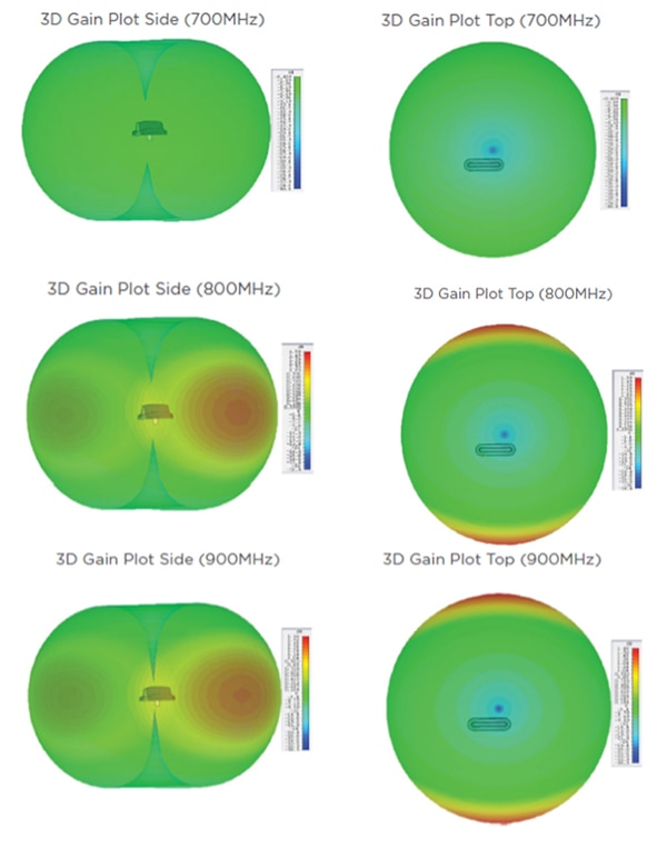
Looking at the lower-band antenna of the 1-2309605-1, its radiation pattern for both top and side orientations is uniform across the bandwidth, from the lower end at around 700 MHz, extending through to the upper frequencies, at about 900 MHz (Figure 3).
 Figure 3: The side (left) and top (right) gain plots of the 1-2309605-1 at 700, 800, and 900 MHz (top row, middle row, bottom row, respectively) show a fairly uniform radiation pattern. (Image source material: TE Connectivity)
At 700 MHz (the low end of the frequency band), the gain in decibels relative to an isotropic antenna (dBi)—a standard metric indicating antenna directivity—is just 1.5 dBi, which represents a fairly uniform radiation pattern. This uniformity and evenness contributes to consistent performance, regardless of antenna orientation. Further, the radiation pattern for the 900 MHz higher-frequency end is also fairly even with gain of just 4.5 dBi.
Another important antenna parameter is the VSWR, which is formally defined as the ratio of the maximum to minimum voltage, or the ratio between transmitted and reflected voltage standing waves on a lossless transmission line. In an ideal scenario, the VSWR would be 1:1. While this is often difficult to achieve, it’s usually acceptable practice to work with a VSWR in the low single digits.
For the 1-2309605-1 M2M MiMo LTE dual antenna, which can handle up to 20 watts of transmit power, the maximum VSWR when measured with 3 meters (m) of RG174 cable is around 3:1 at one end, and closer to 1.5:1 through most of its bands of operation (Figure 4). In general, this is low enough for many of the targeted applications.
 Figure 4: The VSWR (vertical axis) for the 1-2309605-1 M2M MiMo LTE dual antenna as measured with 3 m of RG174 cable shows a low value over the entire active frequency range (x-axis). (Image source: TE Connectivity)
In Figure 4, green is the lower-frequency element #1, red is the higher-frequency element #2, and black is for elements #1 and #2 in free space, while blue is for elements #1 and #2 on a 400 × 400 millimeter (mm) ground plane.
Co-sited antennas
It is possible to co-locate two or more separate antennas to cover multiple bands. However, this leads to several potential problems. First, there’s the obvious issue of space and mounting hardware required on a panel or other surface, as well as the associated installation costs. Second, there are concerns about EM interaction between antennas which will affect their patterns and performance; this constrains how they can be placed with respect to each other. This interaction is measured as antenna isolation, defining to what extent an antenna will pick up radiation from another antenna.
The solution to this quandary is to use a single antenna unit that combines multiple antennas within a single housing or enclosure. Mechanically, this reduces overall size, simplifies installation and antenna-cable routing, and presents a streamlined external appearance.
Electrically, it means that the isolation between the antennas can be measured and specified in advance, minimizing concerns about unexpected or unforeseen interaction. For the 1-2309605-1 M2M MiMo LTE dual antenna, the isolation is at least 15 dB, increasing towards the centers of both bands which the unit serves (Figure 5).
 Figure 5: The isolation (y-axis, dB) between the two antennas within the 2309605-1 M2M MiMo LTE dual antenna module is 15 dB or better, measured as a function of frequency (x-axis, MHz). (Image source: TE Connectivity)
An active receive-antenna function
In addition to the two bands covered by the 1-2309605-1 dual antenna, many applications such as asset tracking also need to receive signals from GPS (US), Galileo (Europe), and Beidou (China) GNSS systems for position or timing information. To simplify this task and avoid the need for another external discrete antenna, TE offers the 1-2309646-1. This adds a third, receive-only antenna for GNSS signals between 1562 – 1612 MHz to the two antennas of the dual-antenna unit.
However, the need to receive GNSS signals adds another challenge for the system designer that goes back to the basics of the transmit versus receive functions. When used for transmitting, the antenna and its feedline are in a deterministic situation. They take the known, controlled, well-defined signal from the transmitter power amplifier (PA) and radiate it. There is little concern about internal noise on that signal, in-band interference, or out-of-band signals between the PA and the antenna.
Due to the reciprocity principle which applies to all antennas, the same physical antenna used for transmitting can be used for receiving. However, the operating conditions for receiving are quite different than they are for transmitting. Since the antenna is trying to capture a signal with unknowns in the presence of in-band and even out-of-band interference and noise, the desired received signal is not deterministic as it has many random characteristics.
In addition, the received signal strength is low (on the order of microvolts to a few millivolts) and the SNR is also low. For GNSS signals, the received signal power is typically between -127 and -25 dB relative to one milliwatt (dBm), while the SNR is typically between 10 and 20 dB. This fragile signal will be attenuated due to losses in the cable between the antenna and receiver front-end, and it will also have its SNR degraded by unavoidable thermal and other noise in the transmission cable.
For these reasons, the 1-2309646-1 incorporates an LNA as another feature for its third, receive-only GNSS antenna. The LNA provides 42 dB gain for the GNSS signals, thereby significantly boosting the received signal strength. To simplify the use of the LNA, it receives its power (3 to 5 volts DC, at no more than 20 milliamps (mA)) via the amplified RF signal’s coaxial cable using a well-established superimposition technique.
DC power is sent on the cable between the receiver unit to the LNB (Figure 6). The DC power for the LNA (V1) is blocked from reaching the radio head unit (front-end) by small series capacitors (C1 and C2). These capacitors do allow the amplified RF signal from the antenna (ANT1) to pass to the radio head unit (OUT). At the same time, the amplified RF signal is blocked from going back to the power supply V1 by series inductors (chokes) L1 and L2. In this way, DC power to the LNA and amplified RF from the LNA to the radio head unit can share the same interconnection coaxial cable.
 Figure 6: The DC power to the antenna LNA can be superimposed on the cable carrying the antenna/LNA output using a clever arrangement of inductors and capacitors which separate and isolate the DC power and RF signal at each end. (Image source: Electronics Stack Exchange)
Making the physical connection
Any antenna or assembly of antenna elements needs to have a reliable, convenient, and electrically and mechanically secure way to be connected and disconnected from the radio front-end they serve. Further, the complete antenna assembly needs to be protected from the environment and be easy to mount with minimal impact on the mounting surface.
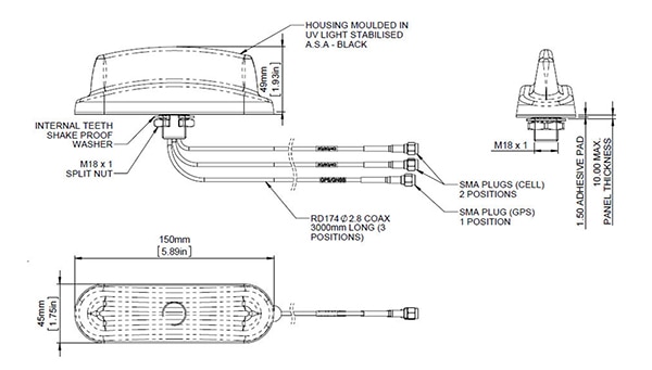
To meet these goals, each band of the two-band 1-2309605-1 and the three-band 1-2309646-1 is equipped with a 3-meter RG-174 coaxial cable, which is terminated with a standard SMA plug (Figure 7). As a result, connecting or disconnecting one or more of the antennas is straightforward and can easily be done in the factory during system assembly, or in the field as an add-on.
 Figure 7: Each antenna within the 1-2309605-1 and 1-2309646-1 has its own RG-174 coaxial cable with SMA plug termination to simplify installation, attachment, test, and disassembly if needed. (Image source: TE Connectivity)
Further, attachment of the multi-antenna module to the system’s surface is eased by use of a single internal 18 mm mounting rod, plus an acrylic adhesive pad around the bottom edge of the antenna housing. Attachment of the antenna is a quick operation that leaves no exposed hardware to rust, loosen, or be incorrectly torqued.
The housing of these antennas is optimized for mobile, high-speed motion applications. The streamlined unit is just 45 mm wide and 150 mm long with rounded edges (similar to the “shark fin” on the roof of automobiles) to minimize its drag coefficient and wind resistance. Further, the UV-stabilized material of the enclosure ensures that exposure to sunlight will not weaken the housing over time.
Conclusion
Mobile, high-speed, multiband wireless connectivity for transportation requires an antenna assembly that can meet demanding electrical, environmental, and mechanical objectives. Two-antenna and three-antenna modules from TE Connectivity provide low band, high band, and optional GNSS band antennas, along with an internal LNA for the latter. These units are equipped with individual coaxial cables and connectors for each antenna, plus a simple surface or panel mount arrangement to facilitate installation and provide critical environmental ruggedness.
Related Content
- TE Connectivity, “Antenna Products”
- DigiKey, “Beyond Wires: Antennas Evolve and Adapt to Meet Demanding Wireless Requirements”
- DigiKey, “Why a Good LNA is Key to a Viable Antenna Front-End”

Disclaimer: The opinions, beliefs, and viewpoints expressed by the various authors and/or forum participants on this website do not necessarily reflect the opinions, beliefs, and viewpoints of DigiKey or official policies of DigiKey.


