Maintaining Electrical Power Quality Within Automated Systems
Contributed By DigiKey's North American Editors
2020-10-20
As covered in a previous DigiKey article on the specifics of dirty utility power, there are half a dozen power-quality issues (including voltage surges, outages, frequency instabilities, and noise) that can arise from fluctuations in the local utility power grid. Further complicating matters is that variations can also originate from within each piece of electrically powered automation equipment. Fortunately, components abound to address such electric-power consistency issues. These power supplies and other power components make machinery perform its best and prevent machinery from having a negative impact on the local utility power grid.
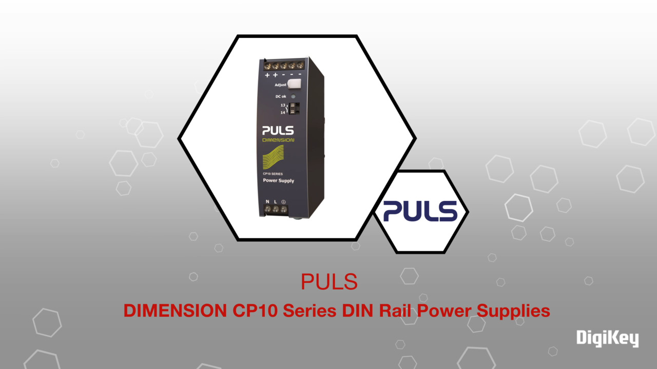
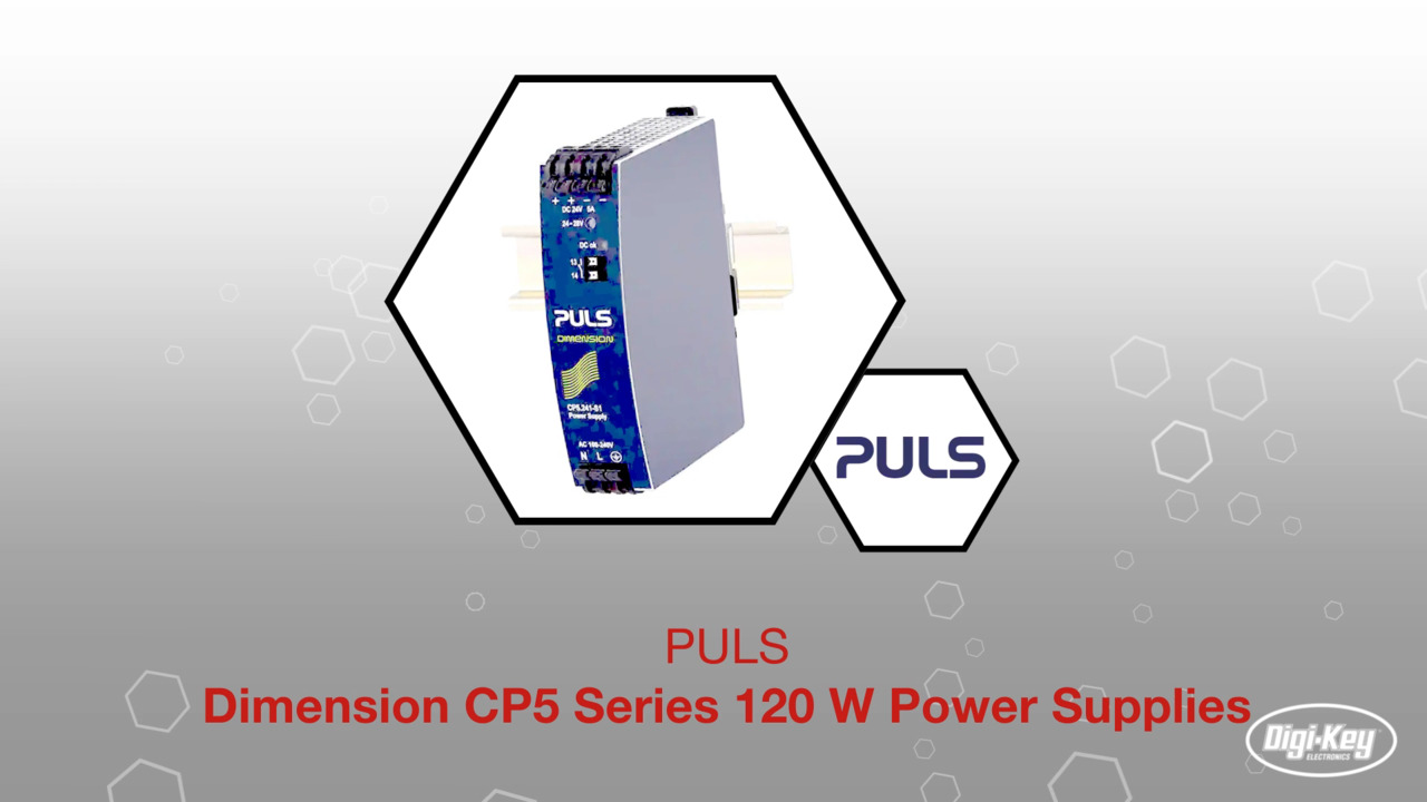
 Figure 1: This PULS CP-Series single-phase power supply mounts to DIN rail so common in industrial automation. Features include high immunity to transients and power surges as well as low electromagnetic emission, a DC-OK relay contact, 20% output power reserves (covered later in this article), and minimal inrush current surge. The specially coated power supply also executes active power factor correction or PFC functions. (Image source: EE World)
The two main types of power-quality problems arising from within equipment are noise and harmonic disturbances.
Electrical noise in electrical power refers to high-frequency voltage variations. High frequency is relative — but always indicates frequencies considerably higher than the system ac frequency. Viewed in the time domain, an ac current should appear as a smooth sinusoidal wave. Noise makes the wave ragged and rough.
There is always some noise in the electrical supplies of machinery caused by the resistance of the conducting wires involved. Such noise is called thermal noise and is generally a negligible disturbance. More significant and potentially detrimental noise is caused by local loads such as welders and electric motors. Noise from such components and systems can often be difficult to quantify — and pose the most risk of causing affected equipment subcomponents to overheat, wear, and even fail.
Electrical harmonics are voltage or current disturbances at frequencies that are integer multiples of the system ac frequency. They are caused by nonlinear loads such as rectifiers, computer power supplies, fluorescent lighting, and certain types of variable-speed electric motors. Current harmonics tend to be larger than voltage harmonics and actually tend to drive the latter.
 Figure 2: Harmonic waveforms are frequency integer multiples of some fundamental waveform that (in electrical power systems) can combine with the fundamental waveform and cause problems. Harmonics typically originate from some electrical load or within an attached piece of machinery. (Image source: Design World)
These electrical harmonics (due to the way they induce heat generation) can dramatically degrade the efficiency and life of electric motors. They may also cause vibrations and torque pulsations in the mechanical output of electric motors, which shortens the life of the power-transmission subcomponents integrated into the motors — especially the shaft-supporting bearings.
Key power-system parameters
Two important specifications for power supplies include the power factor and holdup time.
Power factor is a dimensionless ratio used to describe the difference between true power and apparent power in ac systems. Apparent power is the combination of the true power and the reactive power. Reactive power in turn is drawn from the network, stored momentarily, and then returned without being consumed. This is typically caused by inductive or capacitive loads, which leads to the current and voltage being out of phase. Reactive power increases the load on distribution systems, reduces power quality, and leads to higher energy bills.
Ideally a system will have a power factor of one — meaning there’s no reactive power in the system. Designs with power factors below 0.95 cause increased load on the distribution system and may incur reactive-power charges.
 Figure 3: Shown here is a TML 100C Series, 85-100 Watt AC-to-DC power module from Traco Power. Active power-factor correction (PFC) ensures a power factor of better than 0.95 (for 230 VAC) and better than 0.99 (for 115 VAC). (Image source: Traco Power)
Holdup time is how long a power supply can continue to supply power within its specified voltage after a power outage. Consider the case of uninterruptible power supplies (UPSs) and generators — types of backup power used to ensure continuity of automated operations during blackouts and brownouts. As detailed more fully in this article’s final section, a UPS must supply power for any significant period. But depending on the UPS design, these may introduce a delay of up to 25 msec between a utility-power failure and the UPS initiation of power delivery.
Power-supply holdup time allows the power supply to bridge this gap, largely using power stored in capacitors. In fact, switch-mode power supplies tend to have longer holdup times than linear power supplies due to their higher-voltage capacitors.
Other features to address machine-induced power problems
Grounding, isolation, and filtered power converters provide the foundation for a quality power supply.
Grounding: Proper grounding is essential for a power supply to function correctly. It provides a reference voltage (from which all other voltages are measured) and a return path for electrical current. Read the DigiKey article What You Need to Know about Ground Fault Sensing and Protection for more on this topic.
Isolation: Although non-isolated power supplies can be more energy efficient and compact, isolation between the input and output voltage protects against dangerous voltages passing to the output in the event of a component failure. Isolation may also be required to protect operators from dangerous voltages or to protect equipment from transients and swells.
Forms of isolation include:
- Physical insulation between components
- Inductive coupling through a transformer — power converters that change the voltage of a power system
- Optical couplings — which are most suitable for signal transfer between different parts of a power system while ensuring a very high level of isolation
 converter from Vicor Corp.") Figure 4: Power supplies often function as power converters to either 1) change an ac source’s voltage or frequency or 2) rectify or otherwise convert ac power into dc. Case in point: This 48-V 400-W AC-to-DC pulse-frequency-modulated (PFM) converter from Vicor Corp. has integrated filtering and transient surge protection. One caveat: The Vicor Integrated Adapter (VIA) converter only accepts input from an external rectified sinusoidal ac source — with a power factor maintained by the module. Harmonics conform to IEC 61000-3-2 and internal filtering enables compliance with applicable surge and EMI requirements. (Image source: Vicor Corp.)
Figure 4: Power supplies often function as power converters to either 1) change an ac source’s voltage or frequency or 2) rectify or otherwise convert ac power into dc. Case in point: This 48-V 400-W AC-to-DC pulse-frequency-modulated (PFM) converter from Vicor Corp. has integrated filtering and transient surge protection. One caveat: The Vicor Integrated Adapter (VIA) converter only accepts input from an external rectified sinusoidal ac source — with a power factor maintained by the module. Harmonics conform to IEC 61000-3-2 and internal filtering enables compliance with applicable surge and EMI requirements. (Image source: Vicor Corp.)
Electrical filters and surge suppression: Surge suppression removes transients and swells, protecting electrical equipment from the effects of these overvoltage conditions. In contrast, electrical filters smooth the system voltage to remove noise and harmonics. Read about the filters on industrial power supplies used in large aircraft (with 400 Hz electrical sources) in the digikey.com article Power Supply Operation on a 400 Hz Source. Or consider another electrical-filter type that’s especially common in automated installations near the point of use — LC filters – to complement motor drives. LC filters are a type of tank or resonant circuit (also called a tuned circuit) with an inductor L and a capacitor C to generate output at a set frequency. LC filters for motors usually serve the purpose of converting a drive’s rectangular PWM output voltage into a smooth sine wave with low residual ripple. Benefits include the extension of motor life through avoidance of high dv/dt, overvoltage, overheating, and eddy-current losses.
 Figure 5: This is a Schaffner EMC Inc. LC sine-wave filter to help motor drives deliver smooth sine waves into attached motor windings without voltage peaks. The filter also allows for installations with longer motor-cable lengths. (Image source: Schaffner EMC Inc.)
Surge protectors work by either blocking or shorting current — or combining surge-blocking and shorting measures.
Surge protecting via blocking: Current can be blocked with inductors that damp sudden current changes. However, most surge protectors short when overvoltage occurs, diverting current back into the power distribution lines where it’s dissipated by resistance in the circuit’s wires.
Surge protecting via shorting: Rapid shorting (triggered when voltage exceeds a set level) is done with a spark gap, a discharge tube, or a semiconductor device. Only rarely (during large or very prolonged surges) do surges melt the surge protector’s power lines or internal components. Capacitors may also damp out sudden voltage changes.
Key specifications for surge protectors include clamping voltage, response time, and energy rating. The clamping voltage — also known as let-through voltage — is the maximum voltage allowed to pass through the surge protector. It’s typical for 120 V devices to have a clamping voltage of 220 V. The energy rating (typically in joules) is the maximum power that can be absorbed before components within the surge protector burn out and fail.
An important but often overlooked specification for surge protectors is what happens when the surge protector fails. If a surge exceeds the protector’s energy rating and internal subcomponents fail, that protector will no longer be able to protect against further surges. But this doesn’t mean that power is cut off: some surge protectors (such as some designed to protect server or other electronic memory) will continue to supply power after failure. The only indication that surge protection no longer exists may be a warning light. Other surge protectors do indeed cut power or reduce power transmission when they fail.
UPSs complement generators in critical applications
UPSs and generators for backup power ensure continuity of operations during blackouts and brownouts. UPSs use batteries and are typically designed to provide power for periods of a few minutes to a few hours. Generators use an engine to generate power for prolonged periods, limited only by the fuel available.
UPSs provide an instant response to a power outage, ensuring that the power supply is uninterrupted. Generators on the other hand have a startup time of at least several seconds. For applications where continuous power is required, a UPS must be combined with a generator to supply power while the generator starts up.
 Figure 6: This 24 VDC 5 A uninterruptible power supply (UPS) mounts on DIN rail and provides up to 25 minutes of backup power at full load. (Image source: Phoenix Contact)
UPSs protect equipment from power outages. Offline or voltage and frequency-dependent UPSs are the most cost effective but have two major shortcomings:
- Under normal conditions, offline UPSs pass current directly past the battery to the output. When the UPS circuitry detects a power outage, a switch connects the battery to the output via an inverter. This means that the power may be interrupted by as much as 25 msec.
- Offline UPSs also provide little to no protection against other power-quality issues such as surges and noise.
In contrast, a line-interactive or voltage-independent (VI) UPS works in essentially the same way as a voltage and frequency-dependent UPS, but it has an additional voltage stabilizer to improve power-output quality under normal operation. Such systems still exhibit a switchover time during which power is interrupted — but it’s usually just 5 msec or so, which is well within the holdup time of most power supplies.
Taking power-supply sophistication one step further to provide the greatest protection are online UPSs, also known as voltage and frequency independent UPSs. In UPSs, the load isn’t directly connected to the mains supply but is always drawn from the system battery, which is continuously charged by the mains supply. The mains ac power is transformed to battery voltage and rectified to dc, so it can charge the battery. Power from the battery is then inverted to produce ac and stepped up by another transformer to mains voltage. This means that power quality issues in the supply do not affect the output and very high levels of power quality and protection are provided. However, it also results in considerably lower energy efficiency and higher upfront UPS cost.
For all but the most sensitive and critical loads, an offline UPS coupled with a power supply with sufficient holdup time is a better choice.
Conclusion
Determining a design’s requirements for power quality is the first step to preventing downtime and maintenance costs from dirty utility power, electrical noise, and harmonics. These requirements significantly vary depending on the machine design and its functions. However, once these parameters are defined, design engineers can properly specify power supplies with filters, surge suppression, backup power, and power conditioning. This can profoundly improve the reliability of automated equipment.
Disclaimer: The opinions, beliefs, and viewpoints expressed by the various authors and/or forum participants on this website do not necessarily reflect the opinions, beliefs, and viewpoints of DigiKey or official policies of DigiKey.