Use Power Quality Mitigation Solutions to Protect Water Treatment Plant Electrical Infrastructure
Contributed By DigiKey's North American Editors
2025-03-19
Electricity costs can account for up to 40% of a water treatment plant’s operating budget. This makes it vital that the plant operates with the highest efficiency. However, the plant’s pumps, motor drives, lighting equipment, and compressors will be subject to power quality (PQ) issues such as harmonic distortion, line notching, voltage sags and swells, and electrical noise. These PQ issues cause inefficiencies, outages, and equipment damage.
PQ mitigation equipment resolves problems in water treatment plants. Products such as drive isolation transformers, hardwire regulators, power line conditioners, surge protection devices (SPDs), and active tracking filters work to enhance efficiency, prevent outages, and protect against damage to valuable electrical assets.
This article briefly describes the PQ issues facing designers of electrical equipment in a water treatment plant. It then introduces PQ mitigation equipment from SolaHD that can be applied to alleviate these issues and maximize efficiency.
PQ problems
While the energy supply to a water treatment plant (Figure 1) may be generally reliable, PQ problems often arise. Such issues manifest as unwanted harmonic distortions, voltage sags and swells, and electrical noise.
 Figure 1: The energy supply to a water treatment plant can be subject to PQ issues that can cause inefficiencies, outages, and equipment damage. (Image source: SolaHD)
PQ challenges in a water treatment plant can originate from external sources such as lightning, or internal sources such as the electrical equipment itself. For example, lower-quality variable speed drives can generate harmonic distortions created when a nonlinear load draws current in pulses (Figure 2). Harmonics force conductors to carry currents at frequencies other than the standard supply’s 60 Hz.
 Figure 2: Harmonics are created when a nonlinear load draws current in pulses and forces conductors to carry currents at frequencies other than the standard supply’s 60 Hz. (Image source: SolaHD)
By drawing a nonlinear current at specific points along the voltage sinewave, instead of the complete sinewave, electrical equipment generates harmonic frequencies that are an integer multiple of the fundamental frequency. Low-frequency harmonics (for example, 180 Hz, 300 Hz, or 420 Hz) are caused by low-frequency current distortions and phase-shifted currents flowing through the power system. High-frequency harmonics (between 1 kHz and 3 kHz) are caused by the switching of high currents in high-power, nonlinear electronically switched loads.
Another harmonics phenomenon, line notching, is caused by the switching of current rectifiers in water treatment equipment such as DC motor drives, motor starters, and power supplies. Line notching is typically created by commutation in silicon-controlled rectifiers (SCRs). During the brief time when current is transferred from one conducting SCR to another, a short circuit is created. The new SCR starts conduction while the previous SCR continues to conduct for a brief period. This causes a phase-phase short circuit, typically for a few microseconds (µs), long enough to decrease the voltage. Line notching may occur at any point during the AC half cycle as the angle of commutation is not constant as it changes to meet the load’s requirements.
While there are several external and internal sources of PQ problems, around 80% are caused by voltage sags. The IEEE defines a sag as a 10% to 90% voltage reduction below the normal voltage at 60 Hz. The duration of a sag event is less than 60 seconds (s) but more than 8 milliseconds (ms) (Figure 3).
 Figure 3: A voltage sag is a voltage reduction of 10% to 90% and is responsible for 80% of PQ problems. (Image source: SolaHD)
While voltage swells occur less often than sags, they are just as troublesome. A voltage swell is an overvoltage condition with a temporary voltage level increase from a half frequency cycle to a few seconds (Figure 4). These disturbances can be caused by shutting down large equipment loads in the water treatment plant or other events such as power factor correction (PFC) capacitor switching.
 Figure 4: A voltage swell is a temporary voltage level increase for a duration of a half frequency cycle to a few seconds. (Image source: SolaHD)
Other voltage problems and noise
Electrical equipment and distribution systems can introduce other voltage problems, including voltage transients, interruptions, and unbalance. Also known as voltage spikes, transients are substantial increases in voltage that last for just a few µs (Figure 5). Lightning strikes, mechanical switching, capacitor or capacitor bank switching, power systems reenergizing after a failure, transformer switching, and sudden stoppage of certain equipment are all sources of transients.
 Figure 5: Transients are substantial increases in voltage that last for just a few µs. (Image source: SolaHD)
Voltage interruptions are disruptions in the supply lasting anywhere from a few to tens of seconds. Disruptions for longer than five seconds are typically referred to as sustained interruptions. Typical causes are accidents or equipment failures in the energy utility’s generation or distribution network.
Voltage unbalance is one of the most common problems for three-phase systems. A normal balanced condition is when the three phase voltages are identical in magnitude, and the phase angles are displaced by 120°. Should one phase become too heavily loaded in comparison to the others, the voltage will be lower on that phase, causing an unbalance.
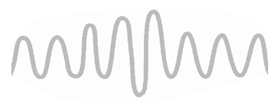
Electrical switching noise can be generated from any equipment when switched on or off due to the influx or outflow of voltage or current. Noise creates rapid voltage variations that produce undesirable effects or damage electronic circuits (Figure 6).
 Figure 6: Electrical noise produces rapid voltage variations that can damage electronic circuits. (Image source: SolaHD)
The impact of PQ problems on plant equipment
PQ problems manifest themselves in various ways that affect water treatment plant equipment's efficiency, reliability, and longevity. For example, harmonics can impact equipment throughout water treatment plants by overheating neutral conductors and transformers, tripping circuit breakers, creating a high neutral current, reducing system capacities, and even loosening electrical connectors.
Line notching creates high-frequency harmonics that can damage sensitive logic and communication electronics in a water treatment facility. Also, the added current flow generated by the notching overloads electromagnetic interference (EMI) filters and line filters. Further, voltage notching can create additional losses in PFC capacitors and lead to elevated operating temperatures.
Problems during a voltage sag include water pumps using AC motors on constant torque load, drawing more current, reducing efficiency, and sometimes tripping overload relays.
Voltage swells do not usually result in an immediate equipment breakdown, but systems can be overstressed and weakened by repeated exposure. Swells can also cause false trips of circuit breakers and other protection devices. A further problem associated with voltage swells is insulation degradation, which can jeopardize the safe operation of a water treatment plant by causing fires.
Power interruptions halt water treatment plant operations and can decrease the lifespan of electrical equipment. Moreover, many motor control circuits and process control systems are not designed to automatically restart after a voltage interruption.
Voltage unbalance can result in severe equipment damage. For example, when an induction motor is fed with an unbalanced voltage, the line currents are usually several times the magnitude of the voltage unbalance. This means a motor fed with a 5% voltage unbalance could have a 20 to 30% current unbalance. The additional current will cause resistive (I2R) losses in the motor, resulting in a temperature rise of tens of °C.
Electrical noise is a serious problem for solid state sensors and controls found in water treatment plants because they operate at fast speeds and extremely low power levels. The lower the signal voltage, the less the amplitude of noise voltage that can be tolerated.
Mitigating PQ problems
Harmonic mitigation can be achieved using drive isolation transformers which perform three essential functions: voltage change, drive-induced ground current reduction, and common-mode noise reduction. The transformers must be able to withstand the heat of nonlinear loads. An example is SolaHD’s 23-22-112-2 drive isolation transformer. This transformer takes a 120 V or 240 V input, provides a 120 V output, and offers an output harmonic distortion (at full load within input range) of 3% of total RMS content. The effective, or RMS, value of a harmonic describes the average power of the harmonic component over one period.
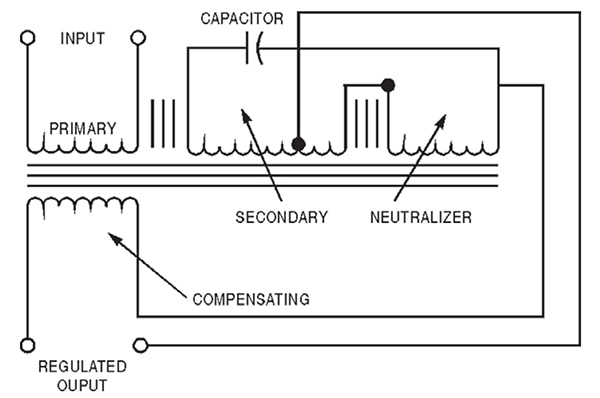
The drive isolation transformer has an almost harmonic-free output because of the addition of a neutralizing coil (Figure 7). To see how this works, consider the device a conventional transformer with the neutralizing coil disconnected. The now open-circuit coil has a voltage induced in it as a portion of the magnetic flux passes through the center leg of the core to the outer legs. This voltage has high odd-harmonic content due to the leakage flux from the output winding.
 Figure 7: The 23-22-112-2 drive isolation transformer has an almost harmonic-free output because of the addition of a neutralizing coil. (Image source: SolaHD)
The leakage flux can return to the output winding by two paths. One path bypasses the neutralizing coil and the other path links to the neutralizing coil. By controlling the reluctance of these magnetic paths, it is possible to control the degree of secondary flux coupled to the neutralizing coil. The neutralizing coil is connected with its polarity additive to the secondary (or output) coil.
The output of this isolation transformer has a constant voltage and is almost completely free of harmonics. The harmonics are still present in the neutralizing coil; however, since the flux from the secondary winding induces those harmonics, the harmonics in each coil are approximately 180° out of phase, resulting in their cancellation.
SolaHD also offers the 63-23-125-4 250 volt-ampere (VA) MCR hardwire regulator (Figure 8) for harmonics reduction. The regulator offers 120 V, 208 V, 240 V, or 480 V inputs with a 120 V output. The output harmonic distortion (at full load within input range) is 3% of total RMS content.
 Figure 8: The 63-23-125-4 MCR hardwire regulator delivers an output harmonic distortion of 3% of total RMS content. (Image source: SolaHD)
The hardwire regulator is built using SolaHD’s ferroresonant transformer technology. Ferroresonance is a transformer design technique that creates two separate magnetic paths in the device with limited coupling between them. One advantage of the design is that the input current contains a negligible harmonic current relative to the fundamental. The output side of the transformer features a parallel resonant tank circuit and draws power from the primary to replace power delivered to the load.
The ferroresonance transformer forms a nonlinear circuit whereby the resonance is used to reduce changes in supply voltage to provide a more consistent voltage to the load.
The transformer’s reluctance changes abruptly above a certain magnetic flux density (saturation). The transformer allows one magnetic path (the resonant path) to be in saturation while the other remains unsaturated. When operating this way, further changes in the primary voltage do not change the saturated or secondary voltage, and regulation is achieved.
Power conditioners are deployed to protect critical process systems against voltage sags.
Voltage regulators and power supplies with sag immunity also protect against drops in the supply voltage.
Voltage swells can be dealt with by SPDs, which can be installed at the service entrance, branch panels, or nearby dedicated sensitive electronic loads. When the voltage surges, the SPD diverts the current into the grounding wire. Power is effectively short-circuited to ground for transient pulses exceeding a threshold while normal current flow is unaffected.
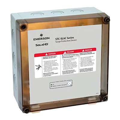
SolaHD’s STCHSP121BT1RU SPD (Figure 9) offers surge suppression for AC power and low-voltage signal lines. The suppressor features the filtering of common-mode and normal-mode noise and metal oxide varistor (MOV) protection. The response time to a transient is less than 5 nanoseconds (ns), and the maximum surge current withstand is 39 kiloamperes (kA). SPDs also offer protection against transient voltages from events such as lightning strikes, though they do not replace a comprehensive lightning protection system.
 Figure 9: The STCHSP121BT1RU SPD suppressor features the filtering of common-mode and normal-mode noise and MOV protection. (Image source: SolaHD)
Noise mitigation is implemented using active tracking filters such as the SolaHD STFV025-24L. This unit continuously tracks the input AC power line and responds when it detects high-frequency noise. The filter eliminates low-voltage/high-frequency noise via a low-pass inductor-capacitor (LC) filter. LC-resistor (LCR) filters are used for low-energy, high-frequency noise reduction. The inductors located on each phase and the neutral conductors are sized to handle the maximum current draw on the line. The response time for the STFV025-24L is <5 ns, and the transient reduction for typical Category A Ringwave (6 kV, 200 A, 100 kHz) is <10 V peak.
Conclusion
It is vital to prevent PQ issues to enhance efficiency, prevent outages, and protect against damage to valuable electrical assets. These issues include harmonic distortion, voltage sags and swells, transient voltages, and electrical noise. Dealing with these requires a multilayered approach. Working with a supplier like SolaHD that can provide a range of protection equipment, including drive isolation transformers, hardwire regulators, power conditioners, SPDs, and active line filters, makes it easier to provide the necessary safeguards.

Disclaimer: The opinions, beliefs, and viewpoints expressed by the various authors and/or forum participants on this website do not necessarily reflect the opinions, beliefs, and viewpoints of DigiKey or official policies of DigiKey.


