Increasing the Resolution of RF Imaging
Contributed By Electronic Products
2015-10-15
Simple RF reflectors have been able to detect the presence of an object in close proximity with extremely-low resolution. Like a one pixel image, it is possible to detect that something is there, but it is impossible to discern shape, size, distance, movement, speed, acceleration, or any other piece of information that is more detailed and resolute. This technology is growing and being adopted in a variety of new applications. Simple proximity radar for blind-spot detection, for example, has made the automobile safer. Initially placed in just a couple of locations around the vehicle, cars now have surround radar as part of collision-avoidance technology and also utilize proximity detection for convenience as well as safety (in automatic lift-gate operation, for example).
However, it doesn’t stop there. Cars that parallel park can leverage this technology in higher resolution and essentially compose a 3-D model in software. A heuristic algorithm (similar to a PCB auto route) finds the best approach, and servo feedback motion control takes over the steering wheel, brakes, and accelerator. This is far beyond a single-pixel-type sensor’s capability and either higher-resolution sensors are needed or beam steering is occurring (or both).
RF has advantages over visible light when it comes to imaging and RF-sensor arrays may supplant or enhance CCD-style visible-light detectors when it comes to processor-based imaging applications. This article looks at the technologies that can be used for higher-resolution RF imaging. It discusses techniques and approaches, as well as the advantages and drawbacks compared to video techniques. All parts, data sheets, tutorials, and development systems referenced here can be found on the DigiKey website.
Out of the shadows
RF has advantages over visible light when it comes to imaging and RF sensors and arrays may supplant or enhance CCD-style visible-light detectors in markets and areas where it makes sense. In both cases, processor-based imaging enhancement and analysis will take place once the finite element “wireframe” of reality is established.
You may not realize that RF proximity technology has been in use for decades, silently monitoring movement in the shadows. Early PIR motion detectors would work but were, shall we say, “flaky.” False alarms were common so the industry came up with dual-technology systems that used microwave pulses to detect change in proximity or movement. Both PIR and microwave sensors must trip together to minimize false alarms.
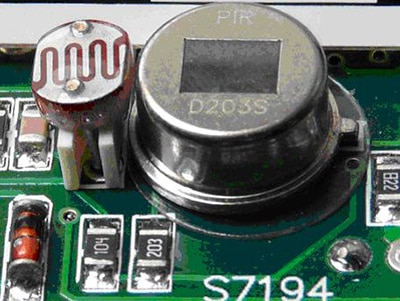
What made these technologies possible for widespread deployment was the development of silicon emitters and detectors, bringing mass production into the equation and eliminating the need for costly alignments or calibrations. Early PIR detectors strategically placed on a PCB enabled the rapid growth of motion-detector products in security systems around the world. Designers soon learned how to compensate for ambient-lighting conditions (Figure 1).
It should be noted here that modern, single-bit PIR detectors are still a vibrant and viable technology and will be useful going forward. For power savings, in many cases only a PIR need be active. When an alert or wakeup condition occurs, then the RF or video or microwave sensor emitters can power up.

Figure 1: The availability of precise monolithic sensors makes mass production feasible. This was true with PIR, CCD arrays, and video sensors and will be true for RF sensors as well. Note the cadmium-sulfide photo-cell to allow ambient-light compensation.
Different approaches to imaging
The most common consumer passive-imaging devices use video detectors as low-cost sensor elements, taking advantage of high-speed DSP processing techniques to reveal details in an image that even the human eye cannot discern. Either a fixed field of views, or moving reflector technology can allow a modern, high-resolution image sensor to capture an image and transport it to an embedded processor, DSP, FPGA, or dedicated image-processing element such as the TI SN65LVDS324ZQLR. A handy little vision-sensor evaluation and development board like the Cognimem 901-3001 may be a good place to start acquiring test images.
Video sensors, however, are generally passive. IR emitters can be used to allow low-light image acquisition, and even variable color emitters can bring out more detail. However, scanning with increased range and resolution usually requires RF or lasers.
The Flying Spot Scanner technology is not new but still has life. These are similar to 1-D line scanners in a fax machine, a bar-graph scanner in a supermarket, or a 2-D scanner such as those used in a pico projector. Like a video-raster scan, lasers trace out a field of view pattern and a simple intensity detector creates a video signal that can be aligned with a display system, or sent to processor memory for analysis.
Early laser printers and scanners actually used motor-based rotating hexagonal or octagonal mirror assemblies to scan out an arc (Figure 2). Initially in 1-D, these intensity modulated beams would charge a cadmium-sulfide drum that could transfer charge to paper before entering a toner section. Once again, applying silicon processes to this function has yielded the digital-light pipe technology that uses Micro Electronic Mechanical Systems (MEMs) to implement moving mirrors on a chip.

Figure 2: Mechanical flying-spot scanners for 1 and 2 dimensions has proven reliable and rugged in bar-code readers and laser printers and can be adapted to use wave-guided RF beams.
Flying-spot scanners use a steady-state beam with no intensity modulation and a detector that is sensitive to the optical or RF wavelength of the emitter. The reflected signal entering the detector creates a video signal whose instantaneous intensity represents the reflectivity of the surface being scanned. In this way, an image in memory is automatically constructed by synchronizing to start-of-line and end-of-line detectors which correspond to memory-address boundaries. The time it takes for a signal to return indicates range.
Moving mirrors can be reflective to different wavelengths like light or RF and moving-mirror monolithics like the Texas Instruments DLP3000FQB and DLP4500FQE can perform the electro-mechanical deflections needed for WVGA and WXGA resolutions, respectively. We know these parts can be price competitive since TV makers use these in high volume. We also know that surface coatings can be used to make surfaces reflective to different wavelengths, and RF beams can be reflected just like other forms of electromagnetic energy.
Several video development and eval systems can be used to test and prototype this approach. Note that the image spectrum in not important to processors and memory; once an image is captured in memory, it doesn’t matter if the source scan was IR, UHF, UV, or gamma rays. The intensity-modulated representation in memory still reflects the real world (no pun intended).
Another thing to note is that the lower-frequency RF makes it easier to detect closer proximity distances than visible light. Lower frequencies can detect phase alignments whereas visible light is much harder to discern. This is why longer-wavelength RF has advantages here when compared with visible light and video-based approaches.
Consider also that frequencies modulated on the RF carrier can add value. Chirp patterns can simplify reflected-time measurements since alignment points can be picked up easily. Also, shifting frequencies can pick up resonances in the reflecting surface. What is more, audio and ultrasonic modulations can allow re-purposing of advanced technology that is already developed.
A sound approach
The same technology used for ultrasonic imaging can be used for RF imaging. In this case, emitters steer a beam to shower a path with the ultrasonically modulated signal and receivers pick it up and pass data to highly integrated processors that can extract detail rather quickly.
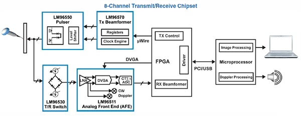
Several monolithics exist that can be used to help include beam steerage such as the TI LM96570SQE/NOPB Configurable Transmit Beam former (Figure 3). Pulse rates up to 80 MHz can launch on individual or all eight channels simultaneously with up to 64-bit patterns with 0.78 nsec timing resolution. A good example of an ultrasound pulser is the Microchip MD1712FG-G which drives two channels to generate five-level waveforms.

Figure 3: Ultrasonic signals from advanced and integrated imagining components can be used as modulated signals over RF, painting an RF-scape field of view. The already available companion imaging chips simplify the designs of back-end image processing.
Similarly, the STMicroelectronics STHV800L Pulser has up to 300 MHz bandwidth and although the high-voltage piezo drive circuits are designed to work with piezo transducers, if these parts do 90 percent of the heavy lifting, then designing an interface to RF stages is comparatively simple. The 8-channel STEVAL-IME009V1 is a quick and handy way to learn, test, and experiment with this technology.
In this regard, several ultrasound imaging devices can be used for rapid prototyping and easily coupling to RF stages. Once you have been able to construct an image in memory, a lot of the ground work has already been laid for RF imaging at higher resolutions.
Antennas up
Several other beam-steering techniques can also be used without moving parts, employing antenna elements that can allow directionally-tuned sensitivity or direction of beam control. This, in turn, can permit the design and implementation of an RF flying-spot scanner transmitter, and a high-gain directionally programmed antenna.
When a mesh network is present, another technique can be used to detect motion and movement. This is called tomographic motion detection and it senses disturbances to radio waves as they pass from node to node of a mesh network. These systems have the ability to detect over complete areas because they can sense through walls and obstructions.
Expect more activity in many of these areas as RF-emitter frequencies can be tuned to see through fog (a limitation of video-based systems), and penetrate surfaces (such as an RF stud finder).
For more information about the parts discussed in this article, use the links provided to access product pages on the DigiKey website.
Disclaimer: The opinions, beliefs, and viewpoints expressed by the various authors and/or forum participants on this website do not necessarily reflect the opinions, beliefs, and viewpoints of DigiKey or official policies of DigiKey.


