How To Use Safety-Rated Contactors to Realize Optimal Industrial Safety Solutions
Contributed By DigiKey's North American Editors
2025-05-21
Safety-rated contactors are needed in industrial applications to ensure that machines and systems can be switched to a safe state reliably and predictably, often in case of an operating error or safety function request. The starting point when designing industrial safety systems is determining if the application requires Safety Integrity Levels (SIL) up to SIL 2 as defined in IEC 62061 and/or Performance Level (PL) c from ISO 13849. Some applications require higher levels of safety.
Consider the guidelines in IEC 60947-4-1 that focus on designing and testing low-voltage switches and control devices, and ISO 13849-1 that provides general principles for designing and integrating safety-related parts of control systems, including hardware and software.
This article shows how to architect safety systems using Siemens' 3RT2 safety-rated contactors with fail-safe operation to realize optimal industrial safety solutions. It also reviews achieving higher SIL and PL levels and system integration issues like contactor thermal management and closes with a dive into how to customize a safety solution using accessories like redundant interconnects, surge suppressors, function modules, and more, for additional application and safety optimization.
3RT2 contactors are available with conventional and solid-state operating options, sizes S00 to S2 that can handle up to 37 kW. For contactors with a solid-state operating mechanism, specify the inclusion of an optional remaining lifetime signal.
These contactors meet the requirements of IEC 60947-4-1 category AC-3e for use with high-efficiency IE3 or IE4 motors. They have a variety of auxiliary output configurations, including normally open (NO) and normally closed (NC) contacts that can be used to provide feedback on whether the main circuit is on or off. Feedback for triggering indicator lights, alarms, or other control devices can be used. Examples of 3RT2 contactors include the following:
- 3RT20152AP611AA0 - size S00, rated for 7 A, 3 kW / 400 V, 3-pole, 220 VAC 50 Hz / 240 VAC 60 Hz, auxiliary contacts: 1 NO, with spring-loaded terminals
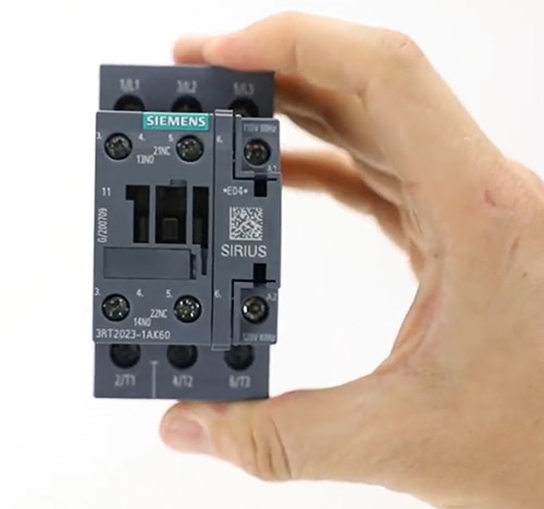
- 3RT20231AK60 - size S0, rated for 9 A, 4 kW / 400 V, 3-pole, 110 VAC 50 Hz / 120 VAC 60 Hz, auxiliary contacts: 1 NO + 1 NC, screw terminals (Figure 1)
- 3RT20281AN20 - size S0, rated for 38 A, 18.5 kW / 400 V, 3-pole, 220 VAC, 50/60 Hz, auxiliary contacts: 1 NO + 1 NC, screw terminals
- 3RT20371KB40 - size S2, rated for 65 A, 30 kW / 400 V, 3-pole, 24 VDC, with integrated varistor, auxiliary contacts: 1 NO + 1 NC, screw terminals
- 3RT20371SF30 - size S2 with F-PCL-IN input, rated for 65 A, 30 kW / 400 V, 3-pole, 83 VAC to 150 VAC/VDC, 50/60 Hz, with integrated varistor, auxiliary contacts: 1 NC, screw terminals
 Figure 1: This size S0 contactor is rated 4 kW and has one NC and one NO auxiliary output. (Image source: Siemens)
Response time is critical to safety
When designing industrial safety solutions, it’s important to understand the impact of overall response time. It consists of several parameters. When performing a risk assessment, response time is defined as the total time within which any hazardous movement must be stopped in the event of a safety requirement. Some of the factors that impact response time include:
- Input reaction time of the sensors in the safety monitoring unit
- Cycle time of the safety program
- Delay time from the communication protocols
- Overtravel time from the inertia of the motor or actuator
- Break time of the contactor
The break time for electromechanical contactors and motor starters is covered by IEC 60947-4-1. The standard outlines requirements for safely breaking currents under various operating conditions.
It also defines utilization categories that classify the type of load and the contactor operating conditions, like AC-3e for high-efficiency motors. The standard includes procedures for testing the break time and other performance characteristics of contactors.
Contactor break time is a critical parameter in safety systems. It’s defined as the time that elapses from removing the coil voltage until the opening of the main contacts, including the opening delay (OD) plus the contact arcing time (AT).
For example, when using a contactor with switching performance as illustrated in Figure 2, the break time, OD + AT, is between 50 and 75 ms. When calculating the total response time, the worst-case values must always be considered - in this case, 75 ms (Figure 2).
 Figure 2: In this example, the total break time for the main contacts (OD + AT) would be specified at 75 ms, the worst-case possibility. (Image source: Siemens)
What safety level is needed?
SIL 2 and PL c designs focus on systems where failures could lead to significant harm, while SIL 3 and PL e designs are for systems where failures could have catastrophic consequences. SIL 3 and PL e systems are more complex, requiring more engineering, integration, and maintenance. SIL 2 and 3 and PL c and e systems are all highly reliable. Still, SIL 3 and PL e systems are designed for even greater reliability, with redundancy and fail-safe mechanisms to mitigate potential failures.
The use of safety-rated contactors is key for simpler and lower-cost safety solutions. These contactors have a dedicated safety input (F-PLC-IN) to ensure they switch to a safe state in the event of a failure, such as a loss of power or control signal error.
The F-PLC-IN input allows for direct connection to a fail-safe controller (F-DQ), enabling the implementation of safety functions like emergency stops or interlocks. Using the F-PLC-IN input eliminates the need for several external components like coupling relays and a dedicated controller (DQ) for the contactor.
With the 3RT2 safety-rated contactors, systems can be designed to meet the requirements of SIL 2 or PL c with only one contactor and SIL 3 or PL e with two contactors in a redundant series configuration. The resulting system simplification can enhance reliability and reduce safety system costs (Figure 3).
 Figure 3: Using 3RT2 safety-rated contactors (bottom) supports higher levels of safety with fewer components compared with non-safety-rated contactors (top). (Image source: Siemens)
Siemens' free-of-charge Safety Evaluation Tool (SET) for IEC 62061 and ISO 13849-1 is TÜV-tested. SET includes a step-by-step safety system evaluation and development environment that allows one to quickly and simply assess the safety functions of a machine. With SET, a report can easily be produced in compliance with the selected standard, which can be integrated into the documentation as proof of safety.
Thermal management considerations
Like any other power-handling device, the designer must consider the heat generated when using 3RT2 contactors. These are highly efficient devices, so there’s not a lot of heat, but there is some. For example, model 3RT20371KB40 is rated for loads up to 30 kW and generates up to 11 W of power loss.
The basic design of 3RT2 contactors is suitable for side-by-side mounting and operation at ambient temperatures from -25°C to +60°C with natural convection cooling. Some of these contractors can be used at temperatures up to +80°C under specific operating restrictions
Between +60°C and +70°C, these contactors can be used continuously with proper current and switching frequency (switches per hour) derating. In addition, a clearance of 10 mm may be required to ensure better heat dissipation with side-by-side mounting.
3RT2 contactors can be used for up to an hour at an ambient temperature between +70°C and +80°C with additional derating. However, the average ambient temperature must not exceed +60°C for any 24-hour period.
These extended temperature recommendations only apply to contactors that don’t contain electronic components. It’s recommended that contactors be used with integrated electronics only up to +60°C to ensure a maximum operating life.
If necessary, one can use the S00 and S0 contactors that don’t include electronics at a minimum ambient temperature of -50°C, if there is no condensation, but the mechanical durability will be reduced by up to 50%. The other performance specifications will be unchanged. Contactors with integrated electronics, or those used with electronic accessories, must not be used at temperatures below -40°C.
Accessories for customizing the safety solution
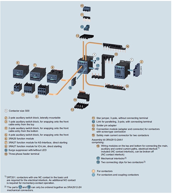
While the contactors are the heart of the system, they often require the addition of accessories to realize an optimal safety solution. For example, 3RT2 contactors in size S00 have numerous choices like auxiliary contacts, auxiliary switches, intelligent link modules, surge suppressors, EMC suppressors, and more (Figure 4).
 Figure 4: The wide variety of available accessories supports customization of safety applications. (Image source: Siemens)
Start with the 3RA29132AA1 wiring kit (parts ⑯, ⑰, and ⑱ in Figure 4). It provides screw terminals for connecting wires and a mechanical interlocking system, ensuring robust electrical and mechanical performance.
If an application requires a series connection of two contactors to achieve SIL 3 or PL e safety, add the 3RA29261A, safety series connector (⑮). Adding a latching block like the 3RT29263AB31 (not shown) enables the contactor to remain in its energized (on) state even after the initial power pulse is removed and can further enhance safety in some applications.
Functional blocks can be added to connect the contactor to the control system. The 3RA27111AA00 (⑧) function module can enable an IO-Link connection. The 3RA27122AA00 module (⑦) adds an AS-Interface that can connect with higher-level fieldbuses like PROFINET. Function modules like the 3RA28132FW10 (⑥) can be used for control tasks like direct-on-line start, reversing start, and star-delta (wye-delta) start.
There is also an option to add auxiliary switch blocks with smaller contacts to implement functions like interlocking, sequencing, and monitoring the status of the main contractor. The auxiliary contacts are available in various configurations, like lateral or front mounting, with NO or NC contacts and various pole numbers. For example, 3RH29111DA02 (②) is a two-pole laterally-mounted model, and 3RH29111NF02 (④) is a two-pole front-mounted configuration.
For enhanced system performance, add an EMC suppressor module like the 3RT29161PA2 (not shown) that uses RC elements to suppress voltage surges, especially when switching off inductive loads like motors, helping prevent coil damage and reducing electromagnetic interference. A surge suppressor like the 3RT29261CD00 (⑨) can protect the coil using a varistor to absorb high voltage spikes that happen when the coil is de-energized.
Conclusion
The 3RT2 series from Siemens is available in sizes S00 to S2 that can handle up to 37 kW. These safety-rated contactors enable the development of safety systems with ratings from SIL 2 and PL c, up to SIL 3 and PL e. Many accessories, like intelligent link modules, auxiliary contacts, auxiliary switches, surge suppressors, EMC suppressors, and more, are available for further design and performance refinements.
Recommended reading:
- Enhance Safety and Boost Availability in Industry 4.0 Factories
- Using a Unified Cybersecure Platform to Support Comprehensive Industry 4.0 Connectivity
- How to Connect Legacy Factory Automation Systems to Industry 4.0 without Disruption
- Safely and Efficiently Integrating AMRs into Industry 4.0 Operations for Maximum Benefit
- Supporting Mass Customization, High Quality, and Sustainable Operations in Industry 4.0 Factories
- Optimizing Industry 4.0 Communication Architectures using Multi-Protocol I/O Hubs and Converters
- How to Quickly Install, Connect, and Integrate Single-axis VSDs into Industry 4.0 Automation Systems

Disclaimer: The opinions, beliefs, and viewpoints expressed by the various authors and/or forum participants on this website do not necessarily reflect the opinions, beliefs, and viewpoints of DigiKey or official policies of DigiKey.


