How to Speed System Design, Validation, and Production Test Using Modular Instruments and Software
Contributed By DigiKey's North American Editors
2023-05-24
Numerous test and measurement (T&M) instruments are needed when designing, validating, and production testing components and systems for automotive, consumer, industrial, medical, and other applications. These suites of T&M instruments need to be compact and have high performance. They need low latency plus high channel density and bandwidth. In addition, design needs can change over time, so modularity is a big plus to future-proof the system. In many cases, these T&M activities involve repetitive testing, or collaboration among geographically dispersed teams, making software-defined testing a highly desirable feature.
The use of a group of conventional instruments is a potential solution. However, issues with system integration of devices from a range of makers, including information being presented on multiple screens, software compatibility, masses of cabling, and the amount of space required for numerous discrete instruments, can be challenging.
Instead, T&M system designers can turn to bundles of high-performance modular instruments and other I/O modules with specialized synchronization and key software features, ranging from device validation to automated production testing. These bundled units are available in a compact, five-slot PXI Express measurement system that is controlled with a laptop or desktop computer through a Thunderbolt USB-C port.
This article begins by briefly reviewing the performance metrics of modular instrument systems, including analog instrumentation categories. It then presents a comparison of the performance of various buses for modular instrument systems and looks at the challenges related to increasing resolution and decreasing latencies. It concludes by presenting PXI Programmable Power Supply (PPS) bundles from NI, including modules for digital multimeters, LCR meters, oscilloscopes, multifunction I/O, waveform generators, and source measurement units, along with software tools for automating the T&M process.
What kind of measurement is needed?
The process of determining what type of T&M instrument is needed begins with a couple of basic questions:
- Is the signal being measured an input, an output, or both?
- Is the signal frequency direct current (DC) or alternating current (AC), and if it’s AC, is it in kilohertz (kHz), megahertz (MHz), or gigahertz (GHz)?
The answers to these questions help to determine if the instrument needed is for DC and power, low-speed analog, high-speed analog, or radio frequency (RF) and wireless applications (Table 1).
|
Table 1: There are several basic categories of T&M instruments based on input and output characteristics and performance levels. (Table source: NI)
Analog instrument specs
After determining the general type of instrument needed for a measurement task, it’s time to identify the specific performance requirements including:
- Signal basics include ensuring that: the signal range is large enough to capture the required signals, the impedance supports the loading of the DUT and frequency requirements of the measurement, and the isolation from ground supports the required levels of noise immunity and safety.
- Bandwidth, in kHz, MHz, or GHz, needs to be adequate to handle the signals being measured, and the analog-to-digital converter (ADC) needs to be fast enough in terms of samples per second, such as kilosamples per second (kS/s), megasamples per second, (MS/s), or gigasamples per second (GS/s) to capture the required signal nuances.
- Resolution and accuracy are also important considerations. Is 8-bit, 24-bit or other level of resolution needed? What is the maximum error rate in terms of percentage or parts per million that can be tolerated? Additionally, what is the required sensitivity in absolute units like microvolts (µV) or nanovolts (nV) that is needed?
Various types of T&M instruments require different input isolation and impedance ranges, input coupling and filtering specs, amplifier sensitivities, and measurement resolution and accuracy, as shown in the measurement instrument analog-input path example (Table 2).
|
 Table 2: Different T&M instruments, such as a DMM and an oscilloscope, can require widely varying performance characteristics for a given measurement. (Table source: NI)
Buses, bandwidth, and latency
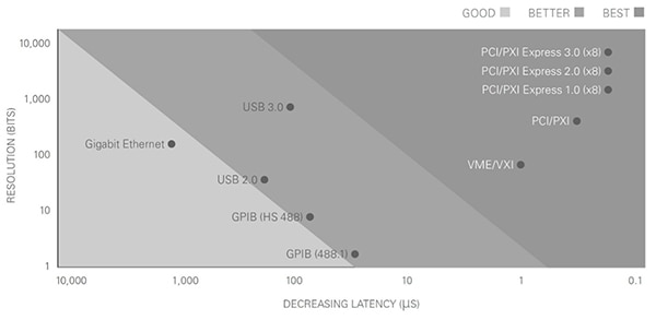
The T&M instruments need to be connected to a controller to form a test system. The requirements for signal bandwidth and latency of the connecting bus are important considerations. Bandwidth measures the speed at which data is transmitted, typically in megabytes per second, while latency measures the delay in the data being transmitted. Commonly used buses have widely varying combinations of bandwidth and latency. Another factor is the transmission distance that the bus supports. For example, the general purpose interface bus (GPIB) and the universal serial bus (USB) can support similar levels of latency, but USB offers higher bandwidth. For its part, Gigabit Ethernet has medium bandwidth and higher latency but can transmit over much longer distances.
When designing T&M systems, PCI and PCI Express are often used. They are designed for short-range links, up to about 1 meter (m), and provide high bandwidth and low latency (Figure 1). An important characteristic of PCI Express is that it provides dedicated bandwidth for each device on the bus. This makes PCI Express the preferred interconnect bus for high-performance and data-intensive applications like real-time T&M systems where it’s necessary to integrate and synchronize the operation of multiple instruments.
 Figure 1: PCI/PXI Express offers the highest performance combination of resolution and latency. (Image source: NI)
T&M instrument bundles
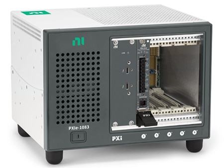
Designers can turn to the PXI PPS bundles from NI as the basis for high-performance T&M systems. The PXI PPS modules provide for the basic power needs of the DUT and can be expanded with numerous T&M modules to support a range of device characterization, design validation, and manufacturing test applications. The chassis supplies up to 58 watts of power and cooling for additional instruments, high-performance PXIe interconnects, and an integrated Thunderbolt link for connecting with an external desktop or laptop computer, acting as the system controller (Figure 2).
 Figure 2: A basic PXI PPS bundle includes a controller, a PPS module, and slots for four more PXI instruments. (Image source: NI)
The PPSs can be used to supply programmable power to a DUT while controlling and monitoring the current and voltage levels to measure power consumption. They have two isolated 60-watt channels with remote sensing to correct for losses in system wiring, with a typical efficiency of 78%. The channels also include output disconnects that can isolate the DUT when it’s not being tested.
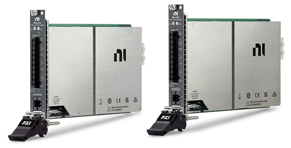
Examples of expandable PXI PPS bundles with 120 watts of power for the DUT include the 867117-01 with a PXIe-4112 two-channel PPS (like model 782857-01) that can deliver a maximum of 1 ampere (A) at 60 volts DC per channel, and the 867118-01 with a PXI2-4113 two-channel PPS (like model 782857-02) that can deliver up to 6 A at 10 volts DC per channel (Figure 3).
 Figure 3: PXI PPS bundles are available with a choice of power supplies having outputs of 60 volts DC (left) or 10 volts DC (right). (Image source: NI)
Jumpstarting T&M system development
NI offers designers a range of PXI bundles to jumpstart their T&M system development efforts. Examples include:
PXI Waveform Generator Bundles that can be used to generate standard functions and user-defined, arbitrary waveforms. The PXI waveform generator bundles feature up to two output channels with bandwidths of up to 80 MHz, a ±12 volt output range, and an 800 MS/s maximum sample rate. For example, the 867119-01 includes a 20 MHz arbitrary function generator.
PXI Oscilloscope Bundles feature up to eight channels that can sample at speeds of up to 5 GS/s with 1.5 GHz of analog bandwidth. Bundle 867010-01 includes a 60 MHz oscilloscope module.
PXI Source Measure Unit (SMU) Bundles, like the 867111-01, are designed to automate DC measurements and tests. The SMUs feature four-quadrant operation, ranges up to ±200 volts and ±3 A, and sensitivity as low as 100 femtoamperes (fA). PXI SMU bundles combine the ability to perform high-power sweeps and low-current measurements.
PXI LCR Bundles such as the 867113-01 can be used to make DC and impedance measurements by combining an LCR meter and an SMU in a single instrument. This instrument provides fA current and femtofarad (fF) capacitance measurements in a single-slot PXI form factor.
PXI DMM Bundles support hand-probed, switched, and automated DMM measurements with high accuracy and resolution of up to 7.5 digits. A high sampling speed allows users to characterize transients without the need for an oscilloscope. Users can also configure triggers for acquisition and/or sequencing. For example, the 867115-01 features a 6.5-digit display.
PXI Nanovolt Meter Bundles are high-resolution analog input modules with up to 28-bit resolution. They include a chopping mode that uses a pair of channels to provide high levels of noise rejection, which enables accurate and repeatable nV measurements and on-board signal averaging and filtering, as well as auto-zero measurement switching. Model 867125-01 features 32 channels, 28-bit resolution, and 2 MS/s sampling.
PXI Multifunction I/O Bundles, like the 867124-01, provide a mix of analog I/O, digital I/O, counter/timer, and triggering functions. The PXI multifunction I/O bundles feature up to four analog output channels, 48 bidirectional digital channels, 80 analog input channels, and a sample rate of 2 MS/s.
Software defines the system
In addition to comprehensive hardware modules, NI offers T&M system designers a choice of software development environments, including InstrumentStudio and LabVIEW.
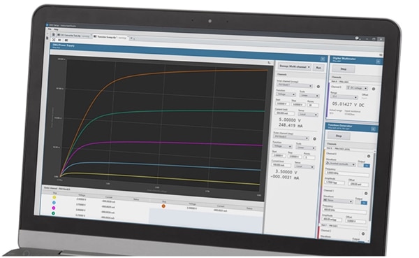
Included with NI PXI instruments, InstrumentStudio gives test engineers a single no-code software environment to monitor and debug automated test systems. Additionally, users can create screens that present data from multiple instruments simultaneously (Figure 4). Tools enable users to capture screenshots and measurement results and save project-level configurations for DUTs that can be reused or shared with other developers.
 Figure 4: InstrumentStudio can present data from multiple instruments on one screen. For example, from an oscilloscope (large left panel), a DMM (top right panel), and a function generator (bottom right panel). (Image source: NI)
LabVIEW is NI’s software-defined testing development environment. With its graphical user interface (GUI), test engineers can quickly develop automated research, validation, and production test systems. At a basic level, LabVIEW’s graphical approach enables nonprogrammers to drag and drop virtual representations of instruments to build T&M programs, create interactive user interfaces, and save data to .cvs, .tdms, or custom-defined binary files.
More advanced programmers can benefit from available drivers for Python, C, C++, C#, .NET, and MATLAB. NI also offers a bundle of software tools for the development of comprehensive T&M environments including:
- TestStand for creating automated test sequences
- G Web development software for building web applications
- DIAdem for interactive data analysis
- FlexLogger for T&M data acquisition and logging
Conclusion
Creating software-defined test environments for design, validation, and production testing of components and systems requires the use of several T&M instruments. Instead of using instruments from multiple suppliers with associated connectivity, cost, and space requirements, test engineers can turn to instrument bundles from NI that can be used to produce compact, flexible, and high-performance testing systems. NI also offers a choice of software environments to speed the development process.
Recommended Reading

Disclaimer: The opinions, beliefs, and viewpoints expressed by the various authors and/or forum participants on this website do not necessarily reflect the opinions, beliefs, and viewpoints of DigiKey or official policies of DigiKey.


