Get a Compact Automated Test System Up and Running Quickly Using PXI Oscilloscope Bundles
Designing a multichannel automated test system with standalone instruments is very inefficient as it duplicates basic functions such as displays, front panels, power supplies, and power cords. Communicating with the rack-and-stack instruments is also unproductive as most of these instruments likely use Ethernet-based LAN Extensions for Instruments (LXI), which is slower and has more programming overhead than some of the faster serial interfaces like Thunderbolt 3.
A better approach is to use modular instruments which offer the needed functionality but in a compact form factor. In such a setup, multiple instruments like oscilloscopes, multimeters, and signal generators fit side-by-side in a common chassis. The instruments communicate internally with a common bus structure which ensures the synchronous operation of all the instruments. They are also controlled by a PC running unifying software that allows all the instruments to be controlled from a common screen.
Let’s look at how this might work using equipment from NI, which has been developing and commercializing automated test and measurement systems for many years. It has simplified test system design by offering a series of oscilloscope bundles using PCI eXtensions for Instrumentation (PXI), a PCI-based platform with a parallel interface that is ideal for creating test systems with multiple instruments and high channel counts.
PXI bundles
On top of the underlying PCI computer bus, PXI adds clocks, synchronization, and triggering buses, along with software configurability to build highly flexible test systems. The PXI chassis supplies power to all the modules and provides internal module-to-module communications, as well as a high-speed module-to-PC communications link.
NI’s bundles include a PXI chassis with five modular instrument slots, a selection of oscilloscope modules, necessary cables or probes, and InstrumentStudio software for control (Figure 1).
 Figure 1: The NI PXI oscilloscope bundle includes the PXI chassis, a PXI oscilloscope module, InstrumentStudio multi-instrument software, and cables. (Image source: NI)
NI’s PXI oscilloscope bundles offer a choice of six oscilloscope modules with channel counts of 2, 4, or 8, with bandwidths ranging from 60 megahertz (MHz) to 1.5 gigahertz (GHz), and sample rates between 60 and 5000 mega samples per second (MS/s) (Table 1). For the chassis, PXIe indicates it supports the faster PCIe serial interface.
| Bundle model | Chassis | Module | Channels | Bandwidth (MHz) | Resolution (bits) | Sample Rate (MS/s) | Memory (Mbytes) |
| 867010-01 | PXIe-1083 | PXIe-5105 | 8 | 60 | 12 | 60 | 128 |
| 867011-01 | PXIe-1083 | PXIe-5110 | 2 | 100 | 8 | 1000 | 512 |
| 867012-01 | PXIe-1083 | PXIe-5111 | 2 | 350 | 8 | 3000 | 512 |
| 867013-01 | PXIe-1083 | PXIe-5113 | 2 | 500 | 8 | 3000 | 512 |
| 867014-01 | PXIe-1083 | PXIe-5172 | 8 | 100 | 14 | 250 | 1500 |
| 867015-01 | PXIe-1083 | PXIe-5162 | 4 | 1500 | 10 | 5000 | 2000 |
Table 1: Summary of NI PXI oscilloscope bundle’s modular oscilloscope specifications. All bundle products use the same PXIe chassis. (Table source: Art Pini, based on NI data)
For example, the 867011-01 uses a PXIe-5110 dual-channel oscilloscope module with a bandwidth of 100 MHz and a sample rate of 1000 MS/s (Figure 2).
 Figure 2: The PXIe-5100 is a dual-channel oscilloscope PXIe module supplied with the 867011-01 PXI oscilloscope bundle, along with two oscilloscope probes. (Image source: NI)
The PXI oscilloscope takes up a single module slot in the chassis, leaving four slots for other instruments. For instance, to get 16 channels, you could use two PXIe-5105 or PXIe-5172 modules. You can also include other PXI instruments and support options, such as multimeters, waveform generators, counters, or power supplies, to name just a few of the many equipment options available.
Using the PXI bundle effectively
There are some rules of thumb concerning digital oscilloscopes. For example, the sample rate must be greater than twice the bandwidth to prevent aliasing. Looking at Table 1, the PXIe-5105 has an analog bandwidth of 60 MHz and a maximum sampling rate of 60 MS/s. The PXIe-5105 avoids aliasing problems by including an internal 24 MHz anti-aliasing filter with a sharp roll-off characteristic, limiting the bandwidth to less than one-half the 60 MS/s maximum sampling rate.
The memory length controls the longest acquisition that can be achieved at the maximum sampling rate. Longer acquisitions require a reduction in the sampling rate. Memory length is most important when dealing with long-waveform events, such as an ultrasonic ranging application in a vehicle that might require a duration in milliseconds. For this application, the 867010-01 PXI oscilloscope running at the maximum sampling rate of 60 MS/s can acquire 2.1 seconds (s) of data in its 128 MB memory.
The resolution of the oscilloscope determines the theoretical dynamic range of the instrument. An 8-bit oscilloscope can ideally digitize a signal between full-scale amplitude (FSA) and FSA/256 (i.e., 2^number bits). So the greater the number of bits, the finer the voltage resolution. This is important in applications where the oscilloscope measures very small signal amplitudes in the presence of large amplitude signals. The ultrasonic ranging application again provides an example. The transmitted pulse will be near FSA, but the reflected echo could be 1000 or more times smaller, requiring a dynamic range of 60 decibels (dB). A rough rule of thumb is that each bit of resolution provides 6 dB of dynamic range, so a 1000:1 dynamic range would need better than 10 bits of resolution.
As in all real instruments, the achievable voltage resolution is generally less than the ideal due to noise and distortion. The figures of merit that are used to measure the true resolution of an oscilloscope are the effective number of bits (ENOB) and the spurious free dynamic range (SFDR) (Figure 3).
 and the spurious free dynamic range (SFDR)") Figure 3: ENOB and SFDR are measures of oscilloscope resolution that account for noise and distortion products like harmonics. (Image source: NI)
Figure 3: ENOB and SFDR are measures of oscilloscope resolution that account for noise and distortion products like harmonics. (Image source: NI)
SFDR, given in dB, measures resolution as being the difference between full scale and the highest spectral peak in the acquired waveform’s frequency spectrum. ENOB determines the resolution, in bits, of an ideal digitizer with a dynamic range between full scale and the root mean square (RMS) noise quantization level. ENOB is always less than the theoretical resolution of the oscilloscope. It is also frequency and amplitude dependent, varying with the input signal frequency.
Software
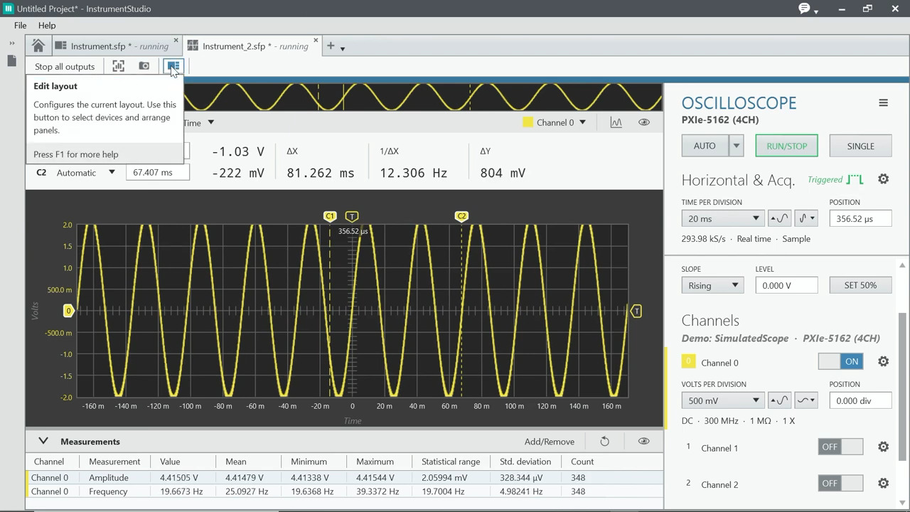
For interactive control of multiple instruments simultaneously, you can use NI’s InstrumentStudio with the PXI oscilloscope bundle (Figure 4). Each instrument has a user-assigned control window allowing for monitoring and debugging of test-system operations.
 Figure 4 : The InstrumentStudio user interface supports interactive control of multiple PXI instruments; each instrument has a user-assigned control window allowing for monitoring and debugging of test system operations. (Image source: Art Pini)
InstrumentStudio enables real-time monitoring and debugging of automated test components, including power supplies, signal sources, multimeters, and other PXI instruments. It also can be used to export instrument configurations directly to more advanced NI test software like LabView.
InstrumentStudio includes measurement and analysis capability for the PXI oscilloscope. It has 35 commonly used measurement parameters like peak-to-peak amplitude, frequency, duty cycle, and time and amplitude cursors. Frequency domain analysis in the form of a fast Fourier transform (FFT) function with averaging is available to provide spectrum analyzer-like displays. The FFT display can include up to 12 user-placed markers to read the amplitude and frequency of specific peaks on the frequency-spectrum display.
The data link
The PXI chassis is controlled from a PC over a Thunderbolt 3 link that can transmit at a rate of up to 40 gigabits per second (Gbits/s) in each direction simultaneously. The PXI chassis has two Thunderbolt 3 connectors on the front panel of the controller slot. Two Thunderbolt 3 connectors are provided to enable daisy-chain connections to multiple Thunderbolt 3 compatible devices, like an external monitor.
The test system
Taking all these individual pieces and putting them together gives you a very compact test system. The PXI chassis and three modules together (an oscilloscope, a digital multimeter (DMM), and a power supply) are smaller than a single rack-and-stack oscilloscope (Figure 5).
 Figure 5: A typical PXI oscilloscope bundle-based system using a chassis, oscilloscope, power supply, DMM, and InstrumentStudio software, shown alongside the same type of rack-and-stack instruments. (Image source: NI)
The device under test (DUT) in Figure 5 is an Arduino board set up to generate a pulse width modulated (PWM) signal. The power supply generates 5 volts to power it up, the DMM reads the regulated 3.3 volts on the device, and the oscilloscope shows the PWM waveform. Interconnection with the DUT is by means of conventional oscilloscope probes (supplied with the PXI oscilloscopes with BNC input connectors) and conventional test leads. The equivalent rack-and-stack instruments, shown to the right, are significantly larger.
Conclusion
The NI PXI oscilloscope bundles offer a solid base for a compact automated test system. They support multiple channel configurations with up to five individual modular instruments. InstrumentStudio software enables interactive measurements of your DUT in both the time and frequency domains with a complete set of measurement tools, including parameters, cursors, and markers.
About this author

Arthur (Art) Pini is a contributing author at DigiKey. He has a Bachelor of Electrical Engineering degree from City College of New York and a Master of Electrical Engineering degree from the City University of New York. He has over 50 years experience in electronics and has worked in key engineering and marketing roles at Teledyne LeCroy, Summation, Wavetek, and Nicolet Scientific. He has interests in measurement technology and extensive experience with oscilloscopes, spectrum analyzers, arbitrary waveform generators, digitizers, and power meters.

Have questions or comments? Continue the conversation on TechForum, DigiKey's online community and technical resource.
Visit TechForumRelated Blogs


More Blogs from this Author