Apply Benchtop Power Supplies’ Programmability, Networking, and Leadless Remote Sensing Features
Contributed By DigiKey's North American Editors
2020-08-06
Power supplies come in an extremely wide range of ratings, physical sizes, and form factors. While it’s common to optimize for size, efficiency, and cost—especially in power-constrained applications such as wearables—there are applications where the power supply unit (PSU) parameters need to be adjusted once a unit is deployed and in use. This is particularly the case with PSUs for benchtop or automated test applications and environments.
This has given rise to power supplies that provide varying degrees of flexibility in the field, ranging from firmware over-the-air updates for efficiency optimization, to always-on remote monitoring and control to ensure accuracy, scalability, redundancy and effective load balancing of power supply arrays. Programmability features can accelerate product design and evaluation, enhance system functionality, and provide needed flexibility. However, among the ever-increasing array of programmable options available, some in particular stand out.
This article examines the roles, functions, and features of advanced, latest generation PSUs, which are much more than just self-contained, standalone, accurate, responsive power supplies in their own enclosures. It then focuses on the features and capabilities, and subsequent benefits of the latest generation, fully networked, highly programmable PSUs from XP Power as examples.
The PSU compared to the open frame supply
In many designs the AC/DC supply is built or squeezed onto the main pc board or a separate board that is “tucked” into a corner. In other products, however, a distinct, independent, separate power supply unit is needed. These supplies—sometimes called “chassis” or “open frame” supplies—are self-contained and meet the necessary packaging, performance, and regulatory requirements. Many of them are available from multiple suppliers as second or alternate sources with respect to form, fit, and function.
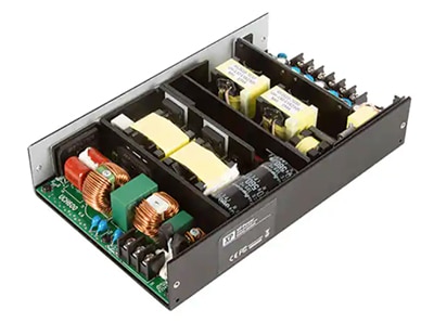
These supplies, typified by units such as the XP Power UCH600PS36, a 36 volt, 4.16 ampere (A), 600 watt (W) open frame supply, have no user interface as none is required (Figure 1). Instead, they are embedded in the end product with no provision for user adjustments once fielded. They have minimal input/output connections: AC input, DC output, and perhaps remote-sensing leads.
 Figure 1: An open frame power supply such as the UCH600PS36 is designed to be embedded in the end product with no need for end-user access or adjustment of its various performance parameters. (Image source: XP Power)
In contrast, engineering projects need a supply with a flexible, easy-to-use interface implemented via a combination of switches, knobs, soft buttons, meters, indicators, and even an alphanumeric readout display. These fully adjustable PSUs are designed to enable convenient adjustment of parameters including output voltage, maximum current, and voltage/current limiting, among other factors. They serve the needs of the engineering team during design, prototype evaluation, and debug phases, and are generally referred to as “benchtop” or “lab” supplies. They may also be rack mounted in a fixed, semi-permanent arrangement for convenience and neatness as part of an automated test equipment (ATE) or other long-term installation (Figure 2).
 Figure 2: “Benchtop” PSUs are used on the engineer’s bench, but they are also often mounted in a rack along with other test units to provide a complete, packaged instrumentation setup. (Image source: UKARANet, United Kingdom Amateur Radio Astronomy Network)
Today’s PSUs must satisfy needs that are more sophisticated than those handled by PSUs of just a few decades ago even as their basic function is the same. Along with the basic voltage and current readouts, and manual adjustment of output voltage value, a PSU must enable other manually directed functions as well as offer remote access.
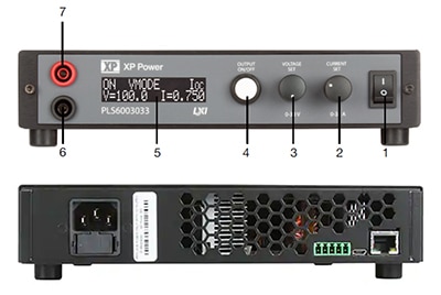
PSUs such as XP Power’s PLS600 Series of programmable DC power supplies do this by allowing adjustment of operating parameters to be done via uncluttered, convenient front panel controls plus various rear panel connectivity options including USB, Ethernet, and analog interfaces (Figure 3). Further, the PSU must monitor its own situation and that of the load, and report the situation directly and remotely, both on demand and as an exception, in order to maintain the confidence in the unit itself as well as the larger system.
 Figure 3: The front panel (top) of units in the PLS600 series is functional and uncluttered while supporting powerful user access and monitoring features; the back panel (bottom) has the AC cord and connectors for USB, Ethernet, and analog interfaces. (Image source: XP Power)
The functions on the front panel (shown as 1 through 7 in Figure 3) are described in further detail in the user manual, but are, in ascending order: power on/off; current set; voltage set; output on/off; the display; and the power output lead sockets.
The PLS600 family consists of five DC output units beginning with the 30 volt PLS6003033 DC and topping out with the 400 volt PLS6004002.5, all with a maximum power rating of 600 watts.
Full programmability brings added benefits
It’s one thing to state that a PSU is “programmable”, but it’s important to clarify what this means for a modern PSU. First, the PSU must have a user-settable rather than fixed output voltage; in many cases, the PSU can also function as a user-settable current source. For convenience, the values of these primary parameters are easily adjusted as needed from the front panel. Along with a digital readout, rotary controls are still the most comfortable way to quickly set, adjust, or “fine tune” the desired value settings.
Among other parameters that users can set are the important overvoltage protection (OVP), overcurrent protection (OCP), and even overpower protection (OPP) values. The latter is useful for applications where the “worry” is not the 600 W power limit of the PLS600 PSU, but the maximum amount of power (voltage × current) that the load should be allowed to draw from the supply to prevent any damage to it.
Often, after making various adjustments to voltage, current, power, or other setpoints under time pressure and stress of debug and test, users may inadvertently neglect to record the values they have actually set for these factors. Due to this and other reasons, the PLS600 PSUs allow quick display of the parameter values. Further, they are all stored internally so they do not need to be reentered on power-up.
Such basic programmability is only the first aspect of a truly versatile PSU. For many test and evaluation situations, there’s a need to have the supply execute a pre-defined real-time “script” independent of a network connection. For this, the PLS600 series provides a sophisticated integrated scripting ability that allows users to write custom programs for the generation of user-defined output profiles to suit a wide variety of unique requirements, and to upload them to the power supply to execute on command.
This allows the supplies to play an advanced role in the larger system and so be an effective element in a product performance sequence or advanced life-cycle test such as a highly accelerated life test (HALT), and possibly of help in finding subtle anomalies related to the end-product power subsystem characteristics.
Connectivity and control from simple to networked
Even though a benchtop PSU should have front panel, hands-on, user-friendly controls for basic and immediate access, those are inadequate for an efficient system-level supply. In addition to the convenient rotary controls for voltage and current adjustment, the PLS600 series also supports remote control via USB, Ethernet, and analog control inputs.
The analog control may seem like an anachronism, but it allows for direct and easy setup of a basic remote-control scenario, and it may be needed in some legacy situations. Note that benchtop instruments tend to have a long life and there are still IEEE-488 General Purpose Interface Bus (GPIB) units in use. The analog control is also convenient when the supply is being used in a closed-loop feedback arrangement where a supply’s voltage must be adjusted in real time based on some sensed or derived voltage.
Beyond that basic analog control, all PLS600 PSUs are LAN eXtensions for Instrumentation (LXI) certified, thereby meeting interoperability standards for LAN-based instruments. Standard LabVIEW and Interchangeable Virtual Instrument (IVI) drivers are available for use with all standard software. The units support Standard Commands for Programmable Instruments (SCPI) and user-developed SCPI-based software is also supported. The USB and Ethernet inputs are SCPI compliant and have LabVIEW drivers available on the National Instruments website. To ensure confidence in setting and readback values, the PSUs include embedded 12-bit digital-to -analog and analog-to-digital converters for accurate measurement and reporting of voltage and current.
The combination of networked, remote setup with the ability to manually change values, or do so under program control, and also report on power supply status and alarm conditions is more than a convenience. It reduces the need for engineers to “babysit” the unit under test and look for and correlate anomalies as they occur. Using this in combination with instruments such as a data logger or a digital oscilloscope with deep memory and suitable triggers makes it practical to execute long-term tests and then download the results for more comprehensive analysis.
Addressing remote sensing and calibration
All current-carrying leads and power rails are subject to current-resistance (IR) voltage (V) drops. A basic calculation using Ohm’s law (V = IR) shows the magnitude of the issue. As a result, the voltage delivered at the load may easily be anywhere from a few millivolts below its nominal value at the supply, to tens or even hundreds of millivolts off.
One way to deal with this drop is to compensate by increasing the nominal voltage at the PSU by an amount equal to the drop, but this is considered poor practice because the IR drop is a function of the current drawn and so will fluctuate. As a result, the voltage at the load may actually be too high at times when the current and resulting IR drop are low.
For this reason, the usual solution is to use remote sensing via two additional leads in a Kelvin sensing arrangement. In this configuration, the actual voltage at the load is sensed and fed back to the supply to dynamically adjust the output so the voltage at the load always has the desired value. This widely used solution is accepted as standard practice and usually works well, but it does have some drawbacks.
First, there’s the need for those two extra leads, which seems like a trivial matter but adds to bench clutter. Second, it’s not always easy to add two additional, low-resistance contacts at the load, especially when the load contacts have not been designed to accommodate them. Anyone that has tried to connect #24 AWG sense leads to screw or other terminals designed for the current-carrying #14/12/10 AWG power supply rail has experienced the difficulty first hand.
Finally, those two extra sense leads may seem like just passive wires, but they are not. Electrically, they form a feedback loop for an amplifier that happens to be a power supply. Any time there is such a feedback loop, there’s the possibility of noise pickup or even oscillation due to the unconstrained and usually poorly defined loop. So, while remote sensing may solve the IR drop problem, it may also cause a more insidious problem of oscillation of the supply output. Additional filtering of the right type may be needed, yet such filtering may also change and degrade the dynamic transient response of the supply.
Remote sensing—without IR drop inducing leads
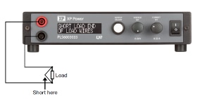
To avoid the mechanical, electrical, and even aesthetic issues associated with remote sensing, the PLS600 series offers an alternative approach using a proprietary technology to digitally compensate for these resistances without the need for any extra wires. In brief, the user invokes the remote sensing mode from the front panel, short-circuits the load wires at the load, and sets the PSU current to at least as much as it is expected that the load will draw (Figure 4).
 Figure 4: The XP Power PLS600 PSUs support a unique scheme for pre-compensation of IR drop, eliminating the need for extra remote-sense leads. (Image source: XP Power)
The PSU measures the output current and the total voltage drop in the load wires, then calculates the resistance of the load wires. The PSU can then adjust the output voltage at its power terminals in real time to correct for the drop in the load cables. As a result, there is no need for separate sense leads in the actual installation.
Advanced PSUs also offer calibration flexibility
Although PSUs such as those in the PLS600 series do not normally need calibration, there may be circumstances where the unit’s output voltage performance needs to be verified and some calibration adjustments are required. To calibrate the output voltage and current and the displayed voltage and current, the PLS600 series requires a calibrated voltmeter and a calibrated current shunt.
The PSU is set to calibrate mode and its output is left open with only the voltmeter attached. In brief, the PSU’s displayed value and the voltmeter value are matched, and the PSU panel button is pushed to register the values. Next, the current shunt is connected across the output and the voltmeter is connected to the shunt. The PSU output is then adjusted until the external voltmeter reads exactly the current displayed on the power supply display (Figure 5). Note that the voltage displayed on the meter will be dependent on the value of the current shunt used, again by Ohm’s law.
 Figure 5: A straightforward two-step process is used to calibrate the XP Power PSUs: an open-circuit output voltage measurement followed by a voltage measurement across a calibrated load shunt. (Image source: XP Power)
How to get more voltage or current
Although PSUs in the PLS600 series are offered in combinations of voltage and current ratings, there will undoubtedly be circumstances where more of one or both of those parameters are needed. The obvious solution is to get a bigger supply, with the downside of added cost. This can be hard to justify as it may only be needed for a short period of time. An alternative is to consider putting two or more of the PLS600 PSUs in series for more voltage or in parallel for more current.
However, getting that increase in voltage or current is not just a matter of connecting two supplies in series or parallel. When they are combined in such a fashion, one of three things will likely happen:
- The configuration will not provide the needed output, is uncontrollable, and the supplies are likely to be damaged
- The configuration works somewhat, but not with the needed performance, accuracy, consistency, or confidence
- It all works just fine either due to luck—generally not a good engineering tactic—or the virtue of deliberate design
Outcomes #1 and #2 are undesirable and unacceptable, although there are ways to work around their shortcomings to some extent, with some carefully selected and rated external components such as current-sharing resistors or isolation diodes (Figure 6). A similar scheme is used for voltage pairing. Even if it works, overall performance is limited by the specifications of the lesser of the two supplies and mismatches between the added components and degraded by those components as well.
 Figure 6: External components such as current-sharing resistors (left) or isolation diodes (right) can be used to put two PSUs in parallel for additional current capability, but performance is degraded by doing so. (Image source: XP Power)
As a result, the general idea is that it causes far fewer problems to use a single power supply that is rated for the application rather than two or more in parallel or series. However, that desirable outcome #3 of “working fine” will occur if the supplies are specifically designed for series or parallel operation—as are the PSUs of the PLS600 series family.
To place PLS600 PSUs in parallel or series, one power supply must be set up to be the master and the rest of the power supplies must be set up as slaves. Up to two supplies (and they must be identical) can be connected in series for voltage boost, while up to four identical units can be used in parallel for current boost. Setup and designation of the master and slave units is done via front panel control, and there are some maximum limits that must be understood for both safety and performance reasons.
Rack and stack for convenience, discipline, efficiency
The visual appearance of engineer workbenches ranges from reasonably neat to incredibly untidy. The reality is that many benches start out neat, but often the clutter just “builds up” and the single or multiple PSUs and their leads add to that clutter. In other cases, the PSU is part of an instrumentation assembly that has been rack mounted for one of several reasons:
- It’s part of a freestanding ATE or long-term evaluation project
- To provide system integrity and enhance reliability by making sure everything has its intended place and all cables are fully dressed and have strain reliefs
- A need for transport and eventual re-installation
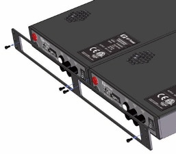
For these reasons, XP Power offers the PLS600 Rack Mount Kit for the PLS600 PSUs (Figure 7).
 Figure 7: The XP Power PLS600 Rack Mount Kit eases installation of a single PLS600 unit or a side-by-side pair of units in a standard chassis equipment rack. (Image source: XP Power)
Since all members of the PLS600 series have the same enclosure size, the kit works for all of them. Installation of a PSU using this kit is a quick and simple task, and the kit allows for two PSUs to be mounted side by side.
Conclusion
Benchtop power supply units are very different in form and function from embedded units that have few or no user controls or adjustments. Benchtop or “laboratory” PSUs are essential instruments for prototype development, debug, and test, as well as fixed-in-place test stands. A well-designed, feature-rich laboratory PSU, such as those in the XP Power PLS600 series, offers both superior performance as well as the additional capabilities and functions needed for efficient and flexible use, ranging from convenient front panel control to networked access and script-driven programmability.
References

Disclaimer: The opinions, beliefs, and viewpoints expressed by the various authors and/or forum participants on this website do not necessarily reflect the opinions, beliefs, and viewpoints of DigiKey or official policies of DigiKey.


