How to Effectively Implement Multi-Connectivity Asset Tracking Applications
2023-01-11
Advanced asset tracking applications, such as livestock monitoring, fleet management, and logistics, automatically capture current status information and position coordinates of tracked objects. A built-in transponder relays its logging data to the cloud and makes it available to the control center or a mobile device. On the factory floor, short-range wireless data updates are often required to exchange logistics data, process history and monitoring data, change configurations, or perform firmware updates in the transponder memory.
Developers of such asset tracking systems are faced with the challenge of designing a multifunctional sensor transponder that communicates via various long and short-range radio protocols, collects a wide range of measurement data, operates for months without battery replacement, and makes all data available via Internet services. Additionally, designers must accomplish all this while lowering costs and reducing time to market.
While the enormity of the task can be overwhelming, designers can save a lot of time and energy by using development kits that already integrate much of the required hardware and software.
This article discusses the technical requirements of advanced asset tracking across multiple applications. It then introduces a multifunctional development kit from STMicroelectronics that significantly reduces the effort required for prototype design, testing, and evaluation. It provides insight into key functional features of the development kit and shows how developers can easily customize the functions of the combined system on chip (SoC) modules without having to code, and then retrieve and visualize the data from the cloud.
Features of a wireless measuring transponder
Asset tracking has a wide range of application areas, each of which requires very specific technical equipment for the transponder and the linked network. Figure 1 lists the technical features of a wireless measurement transponder in four application categories.
") Figure 1: The features of a wireless measurement transponder depend on the asset tracking application. (Image source: STMicroelectronics)
Figure 1: The features of a wireless measurement transponder depend on the asset tracking application. (Image source: STMicroelectronics)
An autonomous transponder carried with the object must detect environmental influences, the position and the status of the object (Sensing, Figure 1), store it, and broadcast it at the next opportunity via any of a variety of wireless interfaces (Connectivity). Signal processing and conversion to various wireless protocols must be handled by a sufficiently powerful microcontroller (MCU) with a high degree of data security ('Processing & security'). The MCU also controls the energy management ('Power management') and thus ensures the transponder battery has a long operating life.
The required data availability of an asset tracking application affects the complexity of the sensors and requires appropriate connectivity. For predictable known transport routes, such as parcel delivery, simply storing the measurement signals in the transponder is sufficient. The data can then be read out at close range using Bluetooth low energy (BLE) or near-field communication (NFC) at the next logistics checkpoint.
In the case of fleet management, as well as logistics and the monitoring of livestock over long distances, the data transfer from the transponder via the cloud to the end-use application should take place as close to real-time as possible. The transponder, therefore, requires a mobile radio interface to cover a wide range. Options include LoRaWAN (long range, wide area network), Sigfox, and Narrowband-Internet of Things (NB-IoT) because these protocols are optimized for low throughput, energy-saving data transfers.
A complete asset tracking ecosystem for less development effort
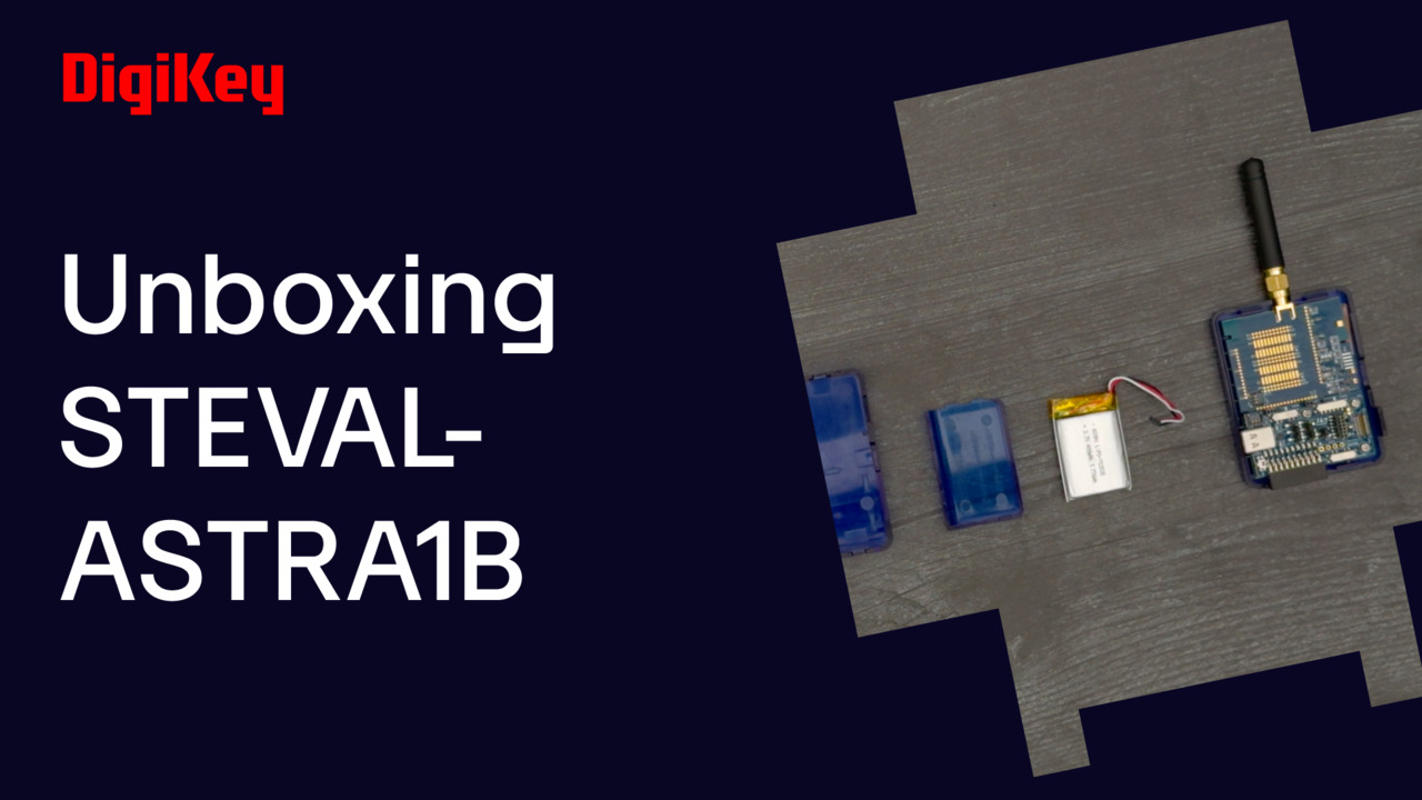
System designers who want to realize their asset tracking application (ASTRA) in a cost and time-efficient way can use the multifunctional STEVAL-ASTRA1B development platform from STMicroelectronics. The platform comprises multiple ICs and SoC modules, greatly simplifying prototyping, programming, testing, and evaluation of innovative tracking and monitoring solutions. The development kit consists of a modular evaluation board, firmware libraries, programming tools, and circuit documentation, as well as an app for mobile devices and a web-based visualization interface (Figure 2).
") Figure 2: The ready-to-use asset tracking ecosystem extends from the wireless measurement transponder to the cloud to the end application, reducing development effort. (Image source: STMicroelectronics)
Figure 2: The ready-to-use asset tracking ecosystem extends from the wireless measurement transponder to the cloud to the end application, reducing development effort. (Image source: STMicroelectronics)
The STEVAL-ASTRA1B board is based on two low-power SoC modules for short and long-range connectivity, along with NFC. Included on board is a module for data security functions. The carrier board has multiple environmental and motion sensors, as well as a Global Navigation Satellite System (GNSS) module that provides position coordinates and enables geofencing. A power management system regulates the operating mode of all device components and controls the power supply. The power supply consists of a switching converter, a battery, and a USB-C charge controller to extend the battery life as much as possible. Upon delivery, the kit includes a 480 milliampere-hour (mAh) lithium polymer (Li-Poly) battery, a case, an SMA antenna (LoRa), and an NFC antenna.
The STEVAL-ASTRA1B board’s ICs and SoCs comprise:
- Two wireless SoCs:
- STM32WB5MMGH6TR: This SoC module based on a 2.4 gigahertz (GHz) wireless ultra-low-power Arm® Cortex®-M4/M0+ MCU acts as the main application processor and supports 802.15.4, BLE 5.0, Thread, andZigbee
- STM32WL55JCI6: This wireless SoC is based on a wireless ultra-low-power Arm Cortex M0+ MCU and supports LoRa, Sigfox, and GFSK at sub 1 gigahertz (GHz) (150 - 960 megahertz (MHz))
- ST25DV64K-JFR8D3: NFC transmitter
- TESEO-LIV3F: GNSS module with simultaneous multi-constellation
- Environmental and motion sensors:
- STTS22HTR: Digital temperature sensor; -40 to 125°C
- LPS22HHTR: Pressure sensor; 26 to 126 kilopascals (kPa), absolute
- HTS221TR: Humidity and temperature sensor; 0 to 100% relative humidity (RH) I²C, SPI ±4.5% RH
- LIS2DTW12TR: Accelerometer X, Y, Z axis; ±2g, 4g, 8g, 16g 0.8 Hertz (Hz) to 800 Hz
- LSM6DSO32XTR: Accelerometer, gyroscope, temperature sensor I²C, SPI output
- STSAFE-A110: Secure element
- Battery-operated solution with smart power management architecture:
- ST1PS02BQTR: Buck switching regulator IC; positive adjustable, 1.8 volt, 1 output, 400 milliamperes (mA)
- STBC03JR: Battery charger IC for lithium ion (Li-ion) or Li-Poly
- TCPP01-M12: USB Type-C and power delivery protection
The evaluation board operates at temperatures from +5 to 35°C and uses the following frequency bands:
- BLE: 2400 MHz to 2480 MHz, +6 decibels referenced to one milliwatt (mW) (dBm)
- LoRaWAN: 863 MHz to 870 MHz, +14 dBm (limited by the firmware)
- GNSS (receiver): 1559 MHz to 1610 MHz
- NFC: 13.56 MHz
The internal structure of the STEVAL-ASTRA1B
The ASTRA transponder behaves like a data logger and divides its data flow into three main blocks, each consisting of hardware and software drivers, as well as the application layer (Figure 3). The data input (Figure 3, left) captures all onboard sensor signals. The central block (Figure 3, center) processes and stores the data. Finally, the stored data is wirelessly broadcast (Figure 3 right). In the event of a reconfiguration, a firmware update, or the writing of process/logistics data, the signal flow runs in the opposite direction.
 Figure 3: Data flow of the wireless measuring transponder: the sensor signals (left) are processed, stored (center), and then sent (right) when the opportunity arises. (Image source: STMicroelectronics)
The FP-ATR-ASTRA1 firmware extends STMicroelectronics' STM32Cube development environment and implements a complete asset tracking application that supports long-range (LoRaWAN, Sigfox) and short-range (BLE, NFC) connectivity. The functional package reads data from environmental and motion sensors, retrieves GNSS geopositioning, and sends everything to a mobile device via BLE, and in parallel to the cloud via LoRaWAN connectivity.
The FP-ATR-ASTRA1 package supports low-power profiles to ensure long battery life for maximum autonomy. It also provides key features such as secure element management, the ability to add custom algorithms, debugging interfaces, and expansion capabilities.
The software package is divided into; Documentation, Drivers & HAL, middleware, and Example Projects. The Projects include source code and compiled binaries for Keil, IAR, and STM32Cube integrated development environments (IDEs). The following five predefined use cases are individually configurable: fleet management, livestock monitoring, goods monitoring, logistics, and custom.
The STEVAL-ASTRA1B operates as a simple state machine that changes its operating mode depending on events. The two main states are designed for full operation (Run) or low power (LP). In Run mode, all functions are active, and all data is broadcast as configured. In the LP state, all components, except the MCU, are set to low-power mode or disabled (Figure 4).
 Figure 4: The two main operating modes of the STEVAL-ASTRA1B are full operation (Run) or LP mode. (Image source: STMicroelectronics)
Pressing the side key triggers the transition between the two states. Another input can be the output of a microelectromechanical systems (MEMS) event or the result of an algorithm. This is just one example of how a state machine can be implemented to change the behavior of the device. Multiple intermediate states can also be implemented to balance system responsiveness and battery life.
Possible events are
- BP: Button pressed event
- SD: Shutdown event
- ER: Error event
- EP: Automatic transition to next step
- RN: Go to full-run command
- LP: Go to low-power command
Retrieve and visualize cloud data
The STEVAL-ASTRA1B transponder has the FP-ATR-ASTRA1 firmware package preinstalled, so environmental measurement signals and GNSS position data can be visualized in minutes.
Using the STAssetTracking mobile app for smartphones and tablets, having Bluetooth enabled and connected to the Internet, the transponder is registered on the TTN (The Things Network) V3 network server as a LoRaWAN participant via the myst.com user account. It is also linked to the DSH-ASSETRACKING web dashboard on Amazon Web Services (AWS).
After TTN registration, the STEVAL-ASTRA1B appears in the updated device list of the mobile app. Pressing the "Start synchronization" button in the <Settings> menu activates the transponder's transmit mode so that it sends out the stored data via BLE and LoRaWAN in parallel. The mobile app can display the measurement data from memory on a dashboard and output the transponder's GNSS position or display it as a marker on a map (Figure 5).
") Figure 5: The mobile app helps to register the transponder at TTN and link it to the cloud dashboard; it visualizes logged sensor values and assists configuration and debugging. (Image source: STMicroelectronics)
Figure 5: The mobile app helps to register the transponder at TTN and link it to the cloud dashboard; it visualizes logged sensor values and assists configuration and debugging. (Image source: STMicroelectronics)
In addition to the ASTRA transponder, the web dashboard can aggregate many other standalone wireless trackers such as the P-L496G-CELL02 (LTE) and the NUCLEO-S2868A2 (Sigfox RF transmitter), or Internet-coupled nodes such as the STEVAL-SMARTAG1 (Wi-Fi), the STEVAL-MKSBOX1V1 (BLE end node), and the STEVAL-SMARTAG1 (NFC end node) in the cloud. This enables the development of a cloud-based multiprotocol wireless ecosystem.
Individual configuration and programming
Once the factory settings of the ASTRA transponder have been successfully evaluated during initial commissioning, the next step is for the developer to customize the transponder to their own asset tracking application.
For minor customization work without additional hardware, it may be sufficient to configure the various parameters and functions via BLE and the mobile app (press the "hammer & wrench" icon in the mobile app, Figure 5).
Another way to configure the project is using a command line and debug console. While a PC terminal program (e.g., Tera Term) communicates via USB through a virtual COM port, the mobile device uses the STBLESensor (ST BLE Sensor) app, and networks via BLE (Figure 6).
, and on a mobile device (right) (click to enlarge)") Figure 6: Command line and debug console on a PC (left), and on a mobile device (right). (Image source: STMicroelectronics)
Figure 6: Command line and debug console on a PC (left), and on a mobile device (right). (Image source: STMicroelectronics)
To reprogram the ASTRA board, as with a firmware update, the integration of other library functions, or the generation of a developer’s own application code, access via the JTAG interface is convenient. For this purpose, the separately available STLINK-V3MINIE debug and programming adapter is connected to the ASTRA board via a 14-pin ribbon cable. An IDE such as Keil, IAR, or STM32Cube installed on a PC can then write compiled binary files to the application program memory or debug program sequences.
The STLINK-V3MINI also provides a virtual COM port interface that allows the host PC to communicate with the target microcontroller via UART.
There are several ways to make firmware updates to the different Arm MCUs:
- The STM32Cube programmer on a PC writes the binary file to the flash memory using a JTAG adapter and an MCU bootloader
- The STM32Cube programmer on a PC writes the binary file to flash memory using USB and an MCU bootloader
- Firmware upgrade over-the-air (FUOTA) is done via BLE using the STBLESensor app on a mobile device
Since the application controller STM32WL55JC (LoRaWAN) acts as master for the STM32WB5MMG (BLE), the respective MCU core to be flashed must be selected via jumpers.
Graphical software configuration using STM32CubeMX
STM32Cube makes developers’ lives easier by reducing development efforts, time, and cost. The IDE covers the whole STM32 MCU portfolio. In addition, STM32CubeMX allows configuration and the generation of C code using graphical wizards. The FP-ATR-ASTRA1 software package expands STM32Cube functionality and can be installed directly into the STM32CubeMX IDE.
Figure 7 shows the STM32CubeMX shell: navigation (left & top), FP-ATR-ASTRA1 pack configuration (middle), and its architecture (right). The FP-ATR-ASTRA1 pack offers three tabs for customization: [Platform Settings], [Parameter Settings], and [ASTRA ENGINE].
") Figure 7: Graphical software configuration using the STM32CubeMX tool: Navigation (left & top), FP-ATR-ASTRA1 pack configuration (middle) and its architecture (right). (Image source: STMicroelectronics)
Figure 7: Graphical software configuration using the STM32CubeMX tool: Navigation (left & top), FP-ATR-ASTRA1 pack configuration (middle) and its architecture (right). (Image source: STMicroelectronics)
Once all the settings are configured, the code can be generated from the STM32CubeMX by pressing the <Generate Code> button. By opening the desired IDE, the firmware code can then be customized, compiled, and flashed on the board.
The generated source code has a modular architecture in terms of hardware blocks and functions. The hardware block management is identified through specific definitions (USE_GNSS). Functions are managed in different files, such as system initialization, state machine configuration, or data management.
Despite the file tree complexity, only a few files are involved in the application configuration of the use cases:
- app_astra.c/.h
This main file is the entry point, and it calls initialization functions inside MX_Astra_Init() (Listing 1)
 function is used for the system initialization") Listing 1: This MX_Astra_Init() function is used for the system initialization. (Listing source: STMicroelectronics)
Listing 1: This MX_Astra_Init() function is used for the system initialization. (Listing source: STMicroelectronics)
- astra_confmng.c/.h
This board configuration manager contains the variables selected by the user to enable/disable each hardware block and use case implementation and configuration. - astra_datamng.c/.h
In this file, the data gathered from the sensors and other inputs are stored in RAM. They are ready to be manipulated, for example, to run a specific algorithm on the data. - astra_sysmng.c/.h
Here, the system-related functions are implemented. The main functionalities are the command line interface, button callbacks, algorithms, LEDs, asset tracking use case management, and the timer management. - SM_APP.c/.h
These files contain the configuration structures of the state machine.
Conclusion
Asset tracking application development is a complex, multi-step process, but the multifunctional STEVAL-ASTRA1B development platform simplifies the task. With all the necessary hardware and software on board, it offers a quick and easy way to visualize the logged data of a wireless transponder in the web interface or via the mobile device app. As shown, developers can simply customize this wireless data logger to their tracking or monitoring application using flexible configuration tools without code programming, or they can use the automatic code generator.
Disclaimer: The opinions, beliefs, and viewpoints expressed by the various authors and/or forum participants on this website do not necessarily reflect the opinions, beliefs, and viewpoints of DigiKey or official policies of DigiKey.