How to Prevent Aliasing in Digital MEMS Sensors
2023-09-15
For the past decade or more, designers of microelectromechanical systems (MEMS) based systems have opted to use digital MEMS sensors rather than analog versions. This trend has been driven because of sensor product availability, feature sets, integration, and cost. When choosing digital MEMS sensors, the engineer is faced with design decisions such as the sensor range, noise, packaging, and current consumption. For inertial MEMS sensors such as accelerometers, designers should also consider the bandwidth characteristics of the sensor in order to avoid aliasing of unwanted signals into the signal chain of the sensor.
This article will discuss the fundamental principles of aliasing in sensor systems and the trade-offs of several methods used to eliminate aliasing error.
Background
MEMS accelerometers1 have become the go-to solution for vibration sensing in applications such Condition Based Monitoring (CbM), Predictive Maintenance (PdM), as well as noise abatement, biometric feedback, and many other applications. Compared to prior solutions which were built around piezoelectric and analog sensors, digital accelerometers offer key advantages such as low power consumption, low cost, and small package sizes. The scalability of digital MEMS accelerometers allows system designers to often use multiple accelerometers in the system and to deploy sensors remotely, at the physical point of vibration. This allows the system to operate at peak performance by detecting inertial motion locally for real time analysis and instantaneous action.
 Figure 1: Typical applications for digital accelerometers. (Image source: STMicroelectronics)
Due to the fully integrated nature of digital accelerometers, designers must consider the sensor bandwidth and frequency response. This is especially true in vibration applications, where the designer must prevent the aliasing of the input frequency into the sensor output.
Nyquist Theorem
Aliasing in accelerometer-based systems occurs when the sensor is sampled at a rate that is too slow to accurately measure the input signal. In MEMS sensors applications such as vibration detection, aliasing can lead to catastrophic failures because the aliased signal may not be present in the actual vibration signal.
An example of aliasing is shown in Figure 2. The sampling rate is less than 2 times the vibration frequency, which has introduced an aliased waveform into the result. The aliased signal is not present in the actual vibration but is an artifact due to the under-sampling of the input vibration. The aliased signal comes from the ADC samples being acquired on the upslope and downslope of the vibration, which is interpolated to represent a different waveform than the actual vibration.
 Figure 2: Aliased result due to low sampling rate. (Image source: STMicroelectronics)
A well-established rule for sampling rate in digital signal processing, known as the Nyquist theorem, is highlighted in equation 1. This rule states that aliasing can be prevented by using a sampling frequency f(sampling) of at least two times the highest frequency (F) in the system.
 Eq.(1)
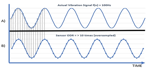
For example, a vibration of 100 Hz would need to be sampled at a minimum of >200 Hz in order to detect the vibration signal without aliasing. As shown in Figure 3, an actual vibration signal is captured correctly when sampled at a rate that is much faster than the minimum frequency. Oversampling is a method of digital filtering, but it should be noted that there may still be some leakage of unwanted signal into the signal chain.
 Figure 3: Oversampling is used to prevent aliasing in the sensor output. (Image source: STMicroelectronics)
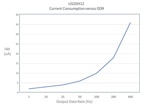
The drawback to using oversampling as a method to reduce aliasing is that the power consumption will be significantly higher because of the high sampling rate. The sampling rate or Output Data Rate (ODR) of a typical sensor has a direct correlation to power consumption as shown in Figure 4. The current consumption increases dramatically at higher sampling rates.
 Figure 4: Current consumption of an accelerometer. (Image source: STMicroelectronics)
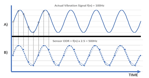
Power consumption can be reduced by reducing the sampling rate closer to the Nyquist frequency as depicted in Figure 5. Here the sampling rate has been reduced to 500 Hz, approximately 2.5 times the target frequency. At 500 Hz the actual vibration waveform can still be recreated with interpolation, and the current consumption will be reduced compared to sampling at 10 times the target frequency.
 Figure 5: Lowering the sampling rate to 2.5x the vibration frequency. (Image source: STMicroelectronics)
This is an improvement over the previous example but there is still a risk that some unanticipated high frequency content on the input could become aliased into the sensor signal chain.
Sampling rate explained
One of the most common questions when it comes to using accelerometers is how to choose the appropriate sampling rate for a particular application. The sampling rate selection is often a trade-off between performance and battery life. A high sampling rate can result in huge data files which can be difficult to manipulate, bog down communications, and can reduce power efficiency. On the other hand, too low of a sampling rate can alias the system as shown in the previous examples.
The good news is that there are well established guidelines for choosing a minimum sampling rate. In applications where power consumption is not constrained, the sampling rate can be set to many times the event frequency. But even with higher sampling rates, digital filtering has a chance of aliasing due to the analog nature of the vibration data and noise.
Anti-aliasing filter (AAF)
In addition to increased power consumption, there are other drawbacks to using digital oversampling. Vibrations are not always perfect sine waves but often have high-frequency components such as harmonics and noise. To reduce these effects, a low-pass filter may be applied to remove any extraneous high frequencies before the signal is sampled. This low-pass filter, also known as an anti-aliasing filter, is embedded in some versions of MEMS accelerometers.
 Figure 6: Analog anti-aliasing (low pass) filter. (Image source: STMicroelectronics)
An anti-aliasing filter works basically like a low-pass filter. The AAF removes high frequency content before it can be sampled by the ADC. The AAF must be located prior to the ADC for the concept to work. If the AAF is placed after the ADC, it then becomes a digital filter, and the drawbacks of the digital filter and oversampling were discussed previously.
Accelerometer family with embedded AAF
The LIS2DU12 is a family of 3-axis digital accelerometers with an embedded anti-aliasing filter in the analog front end. There are three versions of the LIS2DU, each with a unique set of features in addition to the base design. All three devices are packaged in the 2 mm x 2 mm 12 lead MEMS accelerometer package from STMicroelectronics. Each of the devices utilizes the same ultralow-power architecture and the anti-aliasing filter enables a current consumption among the lowest in the market. A comparison of the family is highlighted below.
LIS2DU12: Ultralow-power accelerometer with anti-aliasing and motion detection
LIS2DUX12: Ultralow-power accelerometer with anti-aliasing and Machine Learning Core (MLC) embedded.
LIS2DUXS12: Ultralow-power accelerometer with Qvar, MLC, and anti-aliasing
In the LIS2DU family, the low pass filter is instantiated in the signal chain before the ADC to remove noise before the digital conversion.
In addition to the key addition of the anti-aliasing filter, the LIS2DU12 contains several advanced digital features. These features are intended to offload the main microcontroller by implementing some commonly used functions such as free-fall, tilt, tap-tap detection, orientation, and wake-up. The LIS2DUX12 also contains an embedded machine learning core (MLC) for even more advanced features which can be developed by the design for their particular application.
 Figure:7 LIS2DUX12 accelerometer filtering chain. (Image source: STMicroelectronics)
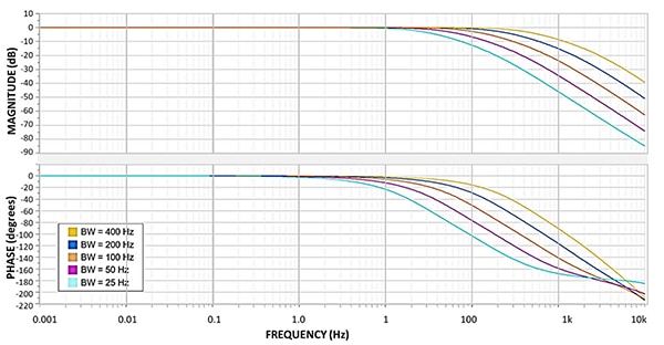
The frequency response of the LIS2DU12 analog anti-aliasing filter is shown in Figure 8. The frequency values from 25 Hz to 400 Hz for each curve below refer to the filtering chain bandwidth values.
 Figure 8: LIS2DU12 analog anti-aliasing (low pass) filter. (Image source: STMicroelectronics)
The net result is that the LIS2DU12 family of accelerometers can operate at much reduced current while achieving the same precision of previous generation accelerometers. In addition to the anti-aliasing filter embedded in all three versions, the LIS2DUX12 and LIS2DUXS12 are the first consumer MEMS devices from STMicroelectronics to include an embedded MLC.
Conclusion
Aliasing is a significant source of error which can lead to a malfunction of the system. In order to mitigate the effects of aliasing, a designer must first understand the system and anticipate the frequency content of all the components in the sensing chain. The Nyquist theorem defines the minimum sample rate for the highest frequency that will be measured.
Oversampling can reduce the effects of aliasing with a trade-off of higher power consumption. The best method to prevent aliasing in many applications is to remove the undesired frequencies by using an anti-aliasing filter before the ADC has converted the samples to the digital domain.
By considering a few guidelines, the designer can choose the proper sampling and filtering techniques for the specific application.
References
- Ultralow-power accelerometer with anti-aliasing & motion detection
- LIS2DU12: advanced ultralow-power 3-axis accelerometer with anti-aliasing filter
- Nyquist-Shannon sampling theorem , Shannon CE. Communication in the Presence of Noise. Proceedings of the IRE [Internet]. 1949 Jan;37(1):10–21.
- LIS2DH12: advanced ultralow-power 3-axisaccelerometer
Disclaimer: The opinions, beliefs, and viewpoints expressed by the various authors and/or forum participants on this website do not necessarily reflect the opinions, beliefs, and viewpoints of DigiKey or official policies of DigiKey.


