Switch Level Modeling and UDP's in Verilog - Part 27
2025-09-15 | By DWARAKAN RAMANATHAN
Introduction to Transistor-Level Modeling and User Defined Primitives (UDPs) in Verilog
When we design digital circuits, we like to be at an abstract level — gates, flip-flops, and modules. However, there are times when we must dive deeper, particularly when precision and optimization are critical. Transistor-level modeling provides designers the ability to design circuits by dealing with the very building blocks of digital architecture: the MOSFETs — the NMOS and PMOS transistors. In addition to this, Verilog provides a very useful feature in the form of User Defined Primitives (UDPs), which enables users to specify custom logic behavior that gate-level modeling may not directly support. In this tutorial, we will discuss the way transistor-level modeling is achieved, how UDPs enhance our design capabilities, and show each concept with simple examples.
Transistor-Level Modeling: NMOS and PMOS Structures
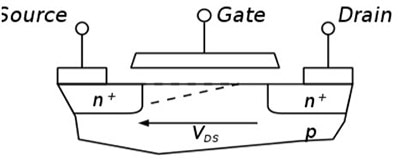
At the transistor level, the circuits are constructed with NMOS (n-channel MOSFET) and PMOS (p-channel MOSFET) devices. Verilog has these primitives available directly with keywords pmos and nmos. These constructs act as switches that are driven by an input signal.
An nmos switch is closed (conducts) when the control signal is logic high (1) and is open (does not conduct) when the control is logic low (0). A pmos switch, however, closes when the control signal is low (0) and opens when the control is high (1). This is a simulation of the real-world behavior of MOSFETs.
Here's a basic example of creating an inverter (NOT gate) at the transistor level:
module inverter(output out, input in);

wire nmos_out;

supply1 Vdd;

supply0 Gnd;

pmos p1(out, Vdd, in);  // pmos(drain, source, gate)

nmos n1(out, Gnd, in);  // nmos(drain, source, gate)

endmodule
In this example, when in is 0, the pmos transistor connects out to Vdd (logic high), and the nmos is off. When in is 1, the nmos transistor connects out to Gnd (logic low), and the pmos is off. This perfectly emulates the behavior of an inverter using real-world transistor action.
Transistor-level modeling enables a much more accurate and detailed modeling of circuits, particularly in simulating real world delay and IC behavior. As the circuits become more complex, though, it becomes too much to manually handle all the connections. That's when another feature comes into play — User Defined Primitives.
Gate-Level Modeling: Abstractions of Logic Simplified
While most control is offered by transistor-level modeling, gate-level modeling is adequate for the overwhelming majority of designs. Gate-level modeling employs the built-in logical primitives such as and, or, not, nand, nor, xor, and xnor to describe the behavior of circuits at a slightly higher level of abstraction. These gates behave precisely like their physical counterparts but without concern for the transistor guts.
Let us consider a simple example of building a 2-input AND gate:
module and_gate(output y, input a, b);

and (y, a, b);  // Built-in 'and' gate primitive

endmodule
Here, the output y will be high (1) only when both a and b are high. This gate-level abstraction is extremely convenient in representing and simulating combinational logic without having to get into transistor intricacies.
To continue gate-level modeling, let's use another example: a 2-input XOR gate. The XOR (exclusive OR) gate generates a 1 output when the two inputs differ.
module xor_gate(output y, input a, b);

xor(y, a, b);  // Standard 'xor' gate primitive

endmodule
Here, if a and b are of opposite values (0 and 1 or 1 and 0), then the output y will be 1. Otherwise, it will be 0. Gate-level modeling enables designers to easily build complex logic functions using these basic building blocks, thus making the process efficient and intuitive.
Hence, gate-level modeling strikes a balance between design speed and level of detail needed, especially in the case of medium-scale designs where it is not necessary to know every single transistor.
User Defined Primitives (UDPs): Simplified Custom Logic
UDPs in Verilog are user-defined logical descriptions that act like built-in primitives (e.g., AND, OR, NOT gates). They are very handy for describing non-standard logic functions or special sequential behavior that will not fit out nicely onto standard gates.
A UDP can be defined using a truth table for combinational circuits or a state table for sequential circuits. Let us first think about what a basic combinational UDP would be.
Assume that we need to construct a simple majority function that returns 1 if and only if at least two of the three inputs are high.
Here's how we can describe it:
primitive majority(output y, input a, b, c);

table

// a  b  c : y

0  0  0 : 0;

0  0  1 : 0;

0  1  0 : 0;

1 0  0 : 0

0  1  1 : 1

1 0  1 : 1;

1  1  0 : 1;

1  1  1 : 1;

endtable

endprimitive
This UDP reads the values a, b, and c and, based on their combination, decides whether the output y should be 0 or 1. Observe how simple it is to implement complicated logic functions now that the table is established — goodbye boring gate wiring!
You may implement this UDP as a regular component within a module:
module use_majority(output y, input a, b, c);

majority m1(y, a, b, c);

endmodule
The beauty of UDPs is that they are reusable and space-efficient. Instead of hard-coding several gates, designers can define a new "primitive" and reuse it across several modules, saving time and making things simpler.
Conclusion:
Transistor-level nmos and pmos primitive modeling gives designers complete control over the behavior of a circuit at its most basic level. Though requiring careful design and attention to detail, it rewards engineers with a glimpse of real-world behavior — parasitic effects, delay, and fine-grained voltage control. Or, User Defined Primitives (UDPs) offer a flexible means to create new logic constructs that reduce complex design patterns to neat, reusable packages. Meanwhile, gate-level modeling is a good middle-ground solution — abstract enough to improve productivity but close enough to hardware to ensure design correctness. Whether you are building custom libraries, exploring new architectures, or optimizing designs for ASICs and FPGAs, understanding and using switch-level modeling, gate-level modeling, and UDPs will be essential tools in your arsenal.