Beginner’s Guide to Logic Gates and Flip-Flops
2025-10-07 | By Zach Hipps
Have you ever wondered how electronics make decisions? It all comes down to logic gates and flip-flops. These are the fundamental building blocks of everything from microcontrollers to memory chips to processors. In this post, we’ll break it all down and simplify it using an interactive demo I built with a couple of switches and an LED.

First, let's talk about logic gates. I’ve drawn out the symbols for three different logic gates on some sticky notes. The first one is the “AND” gate. It has two different inputs and one output. The second one is an “OR” gate. It also has two inputs and one output. The third one is a “NOT” gate, also known as an inverter. It has one input and one output.


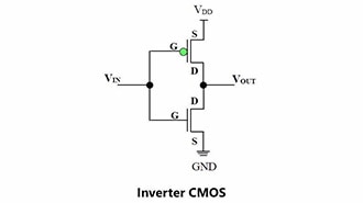
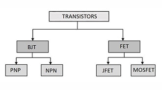
Logic gates aren't just some mystical devices that appeared out of nowhere; they're actually made out of transistors. To show you what I'm talking about, I've drawn a schematic for each of these types of logic gates. The AND gate has two inputs represented by two different switches and one output connected to an LED. The OR gate also has two inputs represented by switches, and its output is connected to another LED. And finally, the NOT gate has one input, represented by one switch, and an LED represents its output.


But how do these logic gates work? How do they actually make decisions? Let's find out by looking at a simulation on the computer. From left to right, we have the AND gate, the OR gate, and the NOT gate. Let’s start playing around with these switches to see how these logic gates behave. With the AND gate, I have two different switches, which means there are four different states. If I close the first switch, the LED remains off. If I open the first one and close the second one, the LED is also off. But if I close both switches, the LED turns on. With the OR gate, when both switches are open, the LED is off. But if I close the top switch, the LED turns on. If I close the bottom switch, it turns on, and if I close both switches, it also turns on. Now, for the NOT gate, which has only one input. When the switch is open, the LED is on; however, when I close the switch, the LED turns off.


I want to write those results down in a table, which is also known as a truth table. A truth table describes the behavior of a logic gate by listing all possible input combinations and the resulting output for each. Instead of referencing voltages, I’ll use the binary number zero for off and the binary number one for on. For the AND gate, the output is only one (on) when both inputs, A and B, are one (on). For the OR gate, the output is one (on) if either input A or B (or both) is one (on). And for the NOT gate, the output is simply the opposite of the input.


I can create new logic gates by combining them. For example, attaching a NOT gate to the output of an AND gate creates a NOT-AND gate, or NAND gate for short. The symbol is very similar to an AND gate, but it features a circle on the output, indicating that the output is inverted. Similarly, you can do the same thing with an OR gate to create a NOT-OR gate, or NOR gate for short. The truth tables for the NAND and NOR gates are the same as the AND and OR gates, but with inverted outputs.
Finally, I would like to introduce one last logic gate, known as an EXCLUSIVE OR gate, or XOR gate. It works very similarly to the OR gate, except that for the output to be one, the inputs must be exclusively different from one another. When the inputs are the same, like 0-0 or 1-1, the output is zero (off). When the inputs are different, the output is one (on). Of course, we can always add an inverter to the output, creating an XNOR gate. These seven logic gates are the fundamental building blocks of all digital design. Notice how all the inverted outputs have a small circle on them, sometimes referred to as a bubble. By combining these logic gates, you can create really complex decision-making behavior.

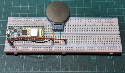
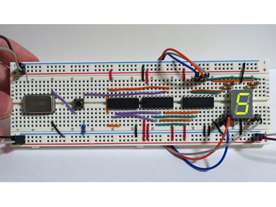
Alright, that's enough theory. I'm tired of drawing things on sticky notes. Let's bring these concepts into the real world. I’m definitely a visual learner; I like having tactile things that I can hold in my hand. That's why I built this digital sandbox, which lets me experiment with all the logic gates we've discussed. It's essentially a microcontroller on a breadboard, featuring two buttons and an LED.


I started with transistors and then converted them into logic gates. Now, let's turn these logic gates into flip-flops. Flip-flops are what enable us to store data and provide our circuits with memory. Logic gates on their own can make decisions, but flip-flops actually remember the state of things.

Let me show you the simplest flip-flop I can make, which is an SR flip-flop. What happens when I combine two logic gates into a circuit like this? I have two NOR gates, which are cross-coupled, meaning the output of one gate is fed into the input of the other. We still have two inputs, a set and a reset, and one output, which I have tied to an LED. When both inputs are inactive (0-0), our output stays the same. Whatever it was before, it will remain the same. However, when we activate the set input, the output gets latched high. Regardless of what happens to the set input, the output will remain latched high. Likewise, we can activate the reset input, and the output goes low. Regardless of the state of the reset input, our output remains latched low. The fourth state, when both the set and reset inputs are activated, is an invalid state. It causes a race condition, and the logic breaks down, so we need to avoid that input state.

Having an invalid state like this is not acceptable, so let's fix that problem by creating a D flip-flop. A D flip-flop improves on the SR flip-flop. Our output only changes on the rising edge of the clock. That means when the clock input changes from a logic low to a logic high, the output will match the input at that moment. The D flip-flop only has valid states because we read our inputs only on the rising edge of the clock. A simple way to think about this is that whenever I receive a rising edge on the clock, the input is mirrored to the output.
Let's take this one step further. We're going to build a JK flip-flop. I'm not kidding, it's called the JK flip-flop. The JK flip-flop is an excellent example of how these components can be used to build bigger and more complex things. It’s similar to the D flip-flop, but now we have two inputs, designated as “J” and “K”. The truth table for this one is very similar to that of the D flip-flop; however, when both inputs are activated (1-1), we can toggle the output.

To summarize what we've learned so far: We can use transistors to build logic gates. Logic gates are what allow electronics to make decisions. Then we can combine logic gates into flip-flops, which store memory. On a basic level, this is how computers make decisions and store information.
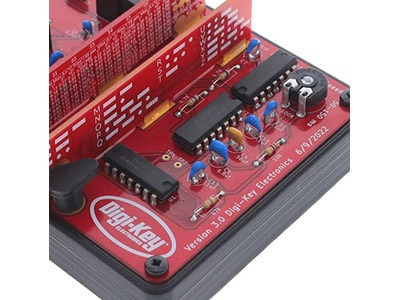
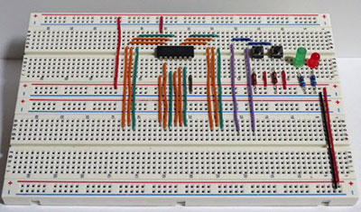
How would you practically use these? The easiest way is to get an integrated circuit chip, like the ones you can get from DigiKey, that has logic gates and flip-flops built into it. That's exactly what I did a long time ago when I was in engineering school. I wanted to build a hands-on, practical way to learn about logic gates and flip-flops, so I dug into the Byte Sized Engineering archives and found the original circuit boards I built while I was in school. This board allowed me to build these circuits in real life. These chips come in both surface-mount and through-hole formats, allowing you to use them to build a circuit board, as I did, or to use them on a breadboard while learning. This was a perfect way for me to understand how all of this works in a real, hands-on way. I've barely scratched the surface of what you can build using logic gates and flip-flops. From here, you could build simple adders or even simple calculators. These are all the building blocks of modern microcontrollers and microprocessors.