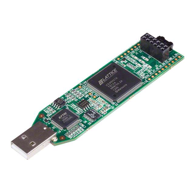
製造商零件編號 ICE40HX1K-STICK-EVN
BOARD EVAL FPGA ICESTICK
Lattice Semiconductor Corporation
License: Attribution
A field-programmable gate array (FPGA) is a reconfigurable integrated circuit (IC) that lets you implement a wide range of custom digital circuits. Throughout the series, we will examine how an FPGA works as well as demonstrate the basic building blocks of implementing digital circuits using the Verilog hardware description language (HDL).
A finite state machine (FSM or sometimes just “state machine”) is a mathematical model used to express how an abstract machine can move sequentially through a series of states. It is a useful design format to help keep processes and code organized.
In the previous tutorial, we looked at using a clock signal on the FPGA board to drive procedural assignments in Verilog. This time, we examine how to use those procedural assignments to create a hardware state machine.
Video
If you have not done so, please watch the following video, which explains the concepts required to complete the challenge. It also demonstrates a working version of the challenge:
Required Hardware
For this challenge, you will need the following hardware:
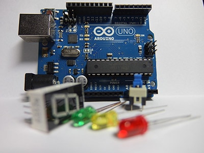
FPGA development board based on the Lattice iCE40. I recommend the iCEstick for this series. However, any of the development boards listed as “supported” by the apio project should work.
(Optional) USB extension cable
Hardware Connections
The PMOD connector at the end of the iCEstick has the following pinout:
A full pinout of the iCEstick can be found here.
Connect 4 pushbuttons to the iCEstick as follows. Note that you do not need pull-up resistors on the buttons. We will use the internal pull-up resistors available in the FPGA.
Resources
The following datasheets and guides might be helpful as you tackle the challenges:
GitHub repository - contains all examples and solutions for this series
Challenge
Button bounce occurs when a switch or pushbutton’s contacts rapidly connect and disconnect in a short amount of time. This generates noise on the button’s line. If you are simply looking for a rising or falling edge to detect a button press, your design (whether hardware or software) might read the button bounce as multiple button presses due to the multiple edges.
In the previous episode, I demonstrated a simple counter using a button as the “clock” input. Unfortunately, due to button bounce, the counter would often skip values, which creates a frustrating user experience.
Your challenge is to design a state machine in your FPGA using Verilog that corrects this button bounce (e.g. a button debouncing circuit). The output should be the same as in the previous episode: 4 LEDs that count up in binary on each button press.
Solution
Spoilers below! I highly encourage you to try the challenge on your own before comparing your answer to mine. Note that my solution may not be the only way to solve the challenge.
[Edit 12/28/2021] IMPORTANT: the solution below is a useful button debouncing design for beginners, but it can lead to errors down the road when we talk about metastability. For a better button debounce circuit that does not rely on an asynchronous clock signal, please see here.
Here is how I designed my state machine for the button debouncing circuit. Note that I used a simple Moore state machine; your solution might be different!
The idea is to wait for some amount of time (say, about 40 ms) after a rising edge on the signal line (inverted button line, so high = button press) and then sample the line again. If it is still high, then we know the button has been pressed. If the input signal line has gone back to low, then we start the state machine over again (and do not increment our LED counter). I set the MAX value to 479,999, which should provide a wait period of 40 ms (assuming a 12 MHz clock) by delaying for 480,000 clock cycles.
Notice that I use 4 states in my FSM. I start with a “HIGH” state to give the state machine a place to reset. If I had just started with the “LOW” state, the FSM would immediately transition to “WAIT” so long as the button was held down. As a result, the LED counter would increment every 40 ms. Having a “repeat while pressed” feature might be desirable in some cases, but it’s not something I wanted here.
The state machine spends 1 clock cycle in the "PRESSED" state where the LED counter (stored in the "led" register) increments by 1.
I used a Moore state machine to make it a little easier to comprehend. You could try recreating this functionality using a Mealy state machine. I encourage you to try it!
Here is my physical constraint file and Verilog code:
solution-button-debouncing.pcf
# Oscillator
set_io              clk         21

# LEDs
set_io              led[0]      99
set_io              led[1]      98
set_io              led[2]      97
set_io              led[3]      96

# PMOD I/O
set_io  -pullup yes rst_btn     78
set_io  -pullup yes inc_btn     79
solution-button-debouncing.v
// One possible way to debounce a button press (using a Moore state machine)
//
// Inputs:
//      clk         - 12 MHz clock
//      rst_btn     - pushbutton (RESET)
//      inc_btn     - pushbutton (INCREMENT)
//
// Outputs:
//      led[3:0]    - LEDs (count from 0x0 to 0xf)
//
// One press of the increment button should correspond to one and only one
// increment of the counter. Use a state machine to identify the edge on the
// button line, wait 40 ms, and sample again to see if the button is still
// pressed.
//
// Date: November 5, 2021
// Author: Shawn Hymel
// License: 0BSD

// Use a state machine to debounce the button, which increments a counter
module debounced_counter (

    // Inputs
    input               clk,
    input               rst_btn,
    input               inc_btn,

    // Outputs
    output  reg [3:0]   led
);

    // States
    localparam STATE_HIGH       = 2'd0;
    localparam STATE_LOW        = 2'd1;
    localparam STATE_WAIT       = 2'd2;
    localparam STATE_PRESSED    = 2'd3;

    // Max counts for wait state (40 ms with 12 MHz clock)
    localparam MAX_CLK_COUNT    = 20'd480000 - 1;

    // Internal signals
    wire rst;
    wire inc;

    // Internal storage elements
    reg [1:0]   state;
    reg [19:0]  clk_count;

    // Invert active-low buttons
    assign rst = ~rst_btn;
    assign inc = ~inc_btn;

    // State transition logic
    always @ (posedge clk or posedge rst) begin

        // On reset, return to idle state and restart counters
        if (rst == 1'b1) begin
            state <= STATE_HIGH;
            led <= 4'd0;

        // Define the state transitions
        end else begin
            case (state)

                // Wait for increment signal to go from high to low
                STATE_HIGH: begin
                    if (inc == 1'b0) begin
                        state <= STATE_LOW;
                    end
                end

                // Wait for increment signal to go from low to high
                STATE_LOW: begin
                    if (inc == 1'b1) begin
                        state <= STATE_WAIT;
                    end
                end

                // Wait for count to be done and sample button again
                STATE_WAIT: begin
                    if (clk_count == MAX_CLK_COUNT) begin
                        if (inc == 1'b1) begin
                            state <= STATE_PRESSED;
                        end else begin
                            state <= STATE_HIGH;
                        end
                    end
                end

                // If button is still pressed, increment LED counter
                STATE_PRESSED: begin
                    led <= led + 1;
                    state <= STATE_HIGH;
                end


                // Default case: return to idle state
                default: state <= STATE_HIGH;
            endcase
        end
    end

    // Run counter if in wait state
    always @ (posedge clk or posedge rst) begin
        if (rst == 1'b1) begin
            clk_count <= 20'd0;
        end else begin
            if (state == STATE_WAIT) begin
                clk_count <= clk_count + 1;
            end else begin
                clk_count <= 20'd0;
            end
        end
    end

endmodule
Synthesize and upload this design to your FPGA. You might need to press the RESET button to put the state machine back in the first state (“HIGH”). Then, try pressing the INCREMENT button to increment the LED counter. You should (hopefully) not see any more skips!
Recommended Reading
The following content might be helpful if you would like to dig deeper:
DigiKey’s example of using a basic D flip-flop to create debounce logic
FPGA 4 Student’s example of another D flip-flop debounce design
Introduction to FPGA Part 4 - Clocks and Procedural Assignments
Introduction to FPGA Part 6 - Verilog Modules and Parameters
Introduction to FPGA Part 7 - Verilog Testbenches and Simulation
Introduction to FPGA Part 9 - Phase-Locked Loop (PLL) and Glitches