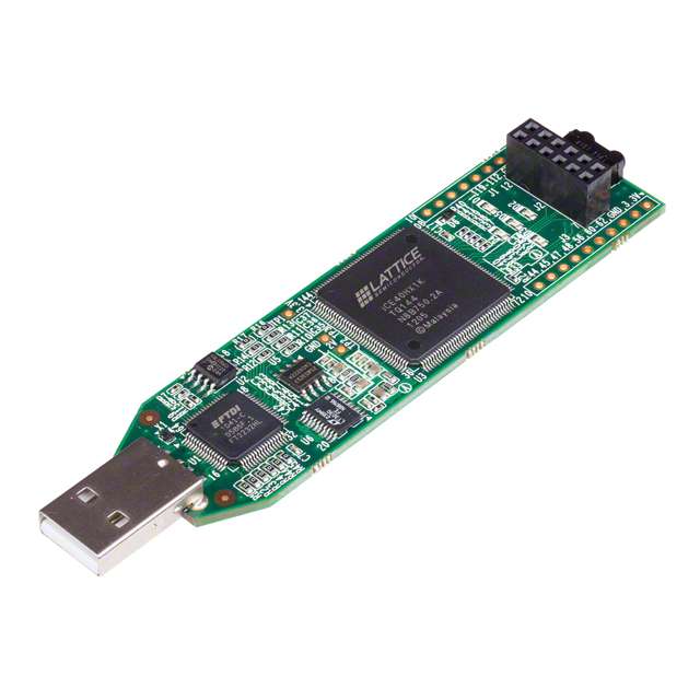
Mfr Part # ICE40HX1K-STICK-EVN
BOARD EVAL FPGA ICESTICK
Lattice Semiconductor Corporation
License: Attribution
A field-programmable gate array (FPGA) is a reconfigurable integrated circuit (IC) that lets you implement a wide range of custom digital circuits. Throughout the series, we will examine how an FPGA works as well as demonstrate the basic building blocks of implementing digital circuits using the Verilog hardware description language (HDL).
When a signal is sampled on a D flip-flop, it must maintain its value for some period of time before the clock transition (setup time) and some time after (hold time). If the input signal changes during one of these windows, it is considered a violation, and metastability could occur.
During a metastable event, the output of the flip-flop is in an unknown state for an indeterminate amount of time. Usually, the output settles on logic high or logic low in a matter of nanoseconds, but the unknown state could, in theory, last forever.
In the previous tutorial, we showed how faster clock speeds can introduce glitches. In this tutorial, we demonstrate a FIFO design that is resilient to metastability and can be used with asynchronous signals or across clock domains.
Video
If you have not done so, please watch the following video, which explains the concepts required to complete the challenge. It also demonstrates a working version of the challenge:
Required Hardware
You will need only the Icarus Verilog simulator and GTKWave waveform viewer for this challenge, as you will be required to simulate gate delays to prove that your design reduces glitches.
Resources
The following datasheets and guides might be helpful as you tackle the challenges:
GitHub repository - contains all examples and solutions for this series
Challenge
As shown in the video, metastability can occur if a setup or hold time violation occurs. This type of anomaly is prevalent when working with asynchronous signals (e.g. signals that are not clocked) or with signals from another clock domain (e.g. signals that are not clocked on the same system clock). You can see metastability in action in this blog post by Colin O’Flynn.
To keep things simple, it’s often advised that FPGA designers should only work with synchronous signals and use one clock for the entire design (or a divided version of the same clock). However, sometimes you must work across clock domains. For example, if you have another device talking to your FPGA over SPI that drives the clock (SCK) line. If the SCK line toggles at 5 MHz and the FPGA clock toggles at 12 MHz, then we must cross clock domains.
One of the most common techniques for working across clock domains is to use a “synchronizer” circuit. This includes a chain of 2 or more flip-flops that operate on the receiving clock signal. You can read more about the synchronizer here.
Additionally, some FPGA block RAM allows you to read and write using different clock signals. This is known as “dual-port RAM.” The block RAM in our iCE40-HX1K offers dual-port capabilities. We can use that to construct a first-in, first out (FIFO) system that allows us to pass data from one clock domain to another. This might include queuing up samples taken from a sensor or acting as a buffer for a communication system (e.g. SPI) that operates on a different clock domain.
Avoiding metastability in a FIFO can be quite difficult. As a result, it often helps to turn to the experts who have spent years perfecting such designs. One such FIFO design can be found here. Clifford Cummings has graciously provided us with a detailed design of his FIFO as well as Verilog code that we can implement.
Your challenge is to implement the FIFO outlined in the above paper, build a testbench for it, and test it with Icarus Verilog.
Solution
Spoilers below! I highly encourage you to try the challenge on your own before comparing your answer to mine. Note that my solution may not be the only way to solve the challenge.
Here is my implementation. Note that I combined some of the modules from Clifford Cummings’s paper, but the design should work the same.
async-fifo.v
// Asynchronous FIFO module
module async_fifo #(

    // Parameters
    parameter   DATA_SIZE = 8,              // Number of data bits
    parameter   ADDR_SIZE = 4               // Number of bits for address
) (

    // Inputs
    input       [DATA_SIZE-1:0] w_data,     // Data to be written to FIFO
    input                       w_en,       // Write data and increment addr.
    input                       w_clk,      // Write domain clock
    input                       w_rst,      // Write domain reset
    input                       r_en,       // Read data and increment addr.
    input                       r_clk,      // Read domain clock
    input                       r_rst,      // Read domain reset

    // Outputs
    output                      w_full,     // Flag: 1 if FIFO is full
    output  reg [DATA_SIZE-1:0] r_data,     // Data to be read from FIFO
    output                      r_empty     // Flag: 1 if FIFO is empty
);

    // Constants
    localparam  FIFO_DEPTH  = (1 << ADDR_SIZE);

    // Internal signals
    wire    [ADDR_SIZE-1:0] w_addr;
    wire    [ADDR_SIZE:0]   w_gray;
    wire    [ADDR_SIZE-1:0] r_addr;
    wire    [ADDR_SIZE:0]   r_gray;

    // Internal storage elements
    reg     [ADDR_SIZE:0]   w_syn_r_gray;
    reg     [ADDR_SIZE:0]   w_syn_r_gray_pipe;
    reg     [ADDR_SIZE:0]   r_syn_w_gray;
    reg     [ADDR_SIZE:0]   r_syn_w_gray_pipe;

    // Declare memory
    reg     [DATA_SIZE-1:0] mem [0:FIFO_DEPTH-1];

    //--------------------------------------------------------------------------
    // Dual-port memory (should be inferred as block RAM)

    // Write data logic for dual-port memory (separate write clock)
    // Do not write if FIFO is full!
    always @ (posedge w_clk) begin
        if (w_en & ~w_full) begin
            mem[w_addr] <= w_data;
        end
    end

    // Read data logic for dual-port memory (separate read clock)
    // Do not read if FIFO is empty!
    always @ (posedge r_clk) begin
        if (r_en & ~r_empty) begin
            r_data <= mem[r_addr];
        end
    end

    //--------------------------------------------------------------------------
    // Synchronizer logic

    // Pass read-domain Gray code pointer to write domain
    always @ (posedge w_clk or posedge w_rst) begin
        if (w_rst == 1'b1) begin
            w_syn_r_gray_pipe <= 0;
            w_syn_r_gray <= 0;
        end else begin
            w_syn_r_gray_pipe <= r_gray;
            w_syn_r_gray <= w_syn_r_gray_pipe;
        end
    end

    // Pass write-domain Gray code pointer to read domain
    always @ (posedge r_clk or posedge r_rst) begin
        if (r_rst == 1'b1) begin
            r_syn_w_gray_pipe <= 0;
            r_syn_w_gray <= 0;
        end else begin
            r_syn_w_gray_pipe <= w_gray;
            r_syn_w_gray <= r_syn_w_gray_pipe;
        end
    end

    //--------------------------------------------------------------------------
    // Instantiate incrementer and full/empty checker modules

    // Write address increment and full check module
    w_ptr_full #(.ADDR_SIZE(ADDR_SIZE)) w_ptr_full (
        .w_syn_r_gray(w_syn_r_gray),
        .w_inc(w_en),
        .w_clk(w_clk),
        .w_rst(w_rst),
        .w_addr(w_addr),
        .w_gray(w_gray),
        .w_full(w_full)
    );

    // Read address increment and empty check module
    r_ptr_empty #(.ADDR_SIZE(ADDR_SIZE)) r_ptr_empty (
        .r_syn_w_gray(r_syn_w_gray),
        .r_inc(r_en),
        .r_clk(r_clk),
        .r_rst(r_rst),
        .r_addr(r_addr),
        .r_gray(r_gray),
        .r_empty(r_empty)
    );

endmodule
r-ptr-empty.v
// Increment read address and check if FIFO is empty
module r_ptr_empty #(

    // Parameters
    parameter   ADDR_SIZE = 4                   // Number of bits for address
) (

    // Inputs
    input       [ADDR_SIZE:0]   r_syn_w_gray,   // Synced write Gray pointer
    input                       r_inc,          // 1 to increment address
    input                       r_clk,          // Read domain clock
    input                       r_rst,          // Read domain reset

    // Outputs
    output      [ADDR_SIZE-1:0] r_addr,         // Mem address to read from
    output  reg [ADDR_SIZE:0]   r_gray,         // Gray address with +1 MSb
    output  reg                 r_empty         // 1 if FIFO is empty
);

    // Internal signals
    wire    [ADDR_SIZE:0]   r_gray_next;    // Gray code version of address
    wire    [ADDR_SIZE:0]   r_bin_next;     // Binary version of address
    wire                    r_empty_val;    // FIFO is empty

    // Internal storage elements
    reg     [ADDR_SIZE:0]   r_bin;          // Registered binary address

    // Drop extra most significant bit (MSb) for addressing into memory
    assign r_addr = r_bin[ADDR_SIZE-1:0];

    // Be ready with next (incremented) address (if inc set and not empty)
    assign r_bin_next = r_bin + (r_inc & ~r_empty);

    // Convert next binary address to Gray code value
    assign r_gray_next = (r_bin_next >> 1) ^ r_bin_next;

    // If the synced write Gray code is equal to the current read Gray code,
    // then the pointers have caught up to each other and the FIFO is empty
    assign r_empty_val = (r_gray_next == r_syn_w_gray);

    // Register the binary and Gray code pointers in the read clock domain
    always @ (posedge r_clk or posedge r_rst) begin
        if (r_rst == 1'b1) begin
            r_bin <= 0;
            r_gray <= 0;
        end else begin
            r_bin <= r_bin_next;
            r_gray <= r_gray_next;
        end
    end

    // Register the empty flag
    always @ (posedge r_clk or posedge r_rst) begin
        if (r_rst == 1'b1) begin
            r_empty <= 1'b1;
        end else begin
            r_empty <= r_empty_val;
        end
    end

endmodule
w-ptr-full.v
// Increment write address and check if FIFO is full
module w_ptr_full #(

    // Parameters
    parameter   ADDR_SIZE = 4                   // Number of bits for address
) (

    // Inputs
    input       [ADDR_SIZE:0]   w_syn_r_gray,   // Synced read Gray pointer
    input                       w_inc,          // 1 to increment address
    input                       w_clk,          // Write domain clock
    input                       w_rst,          // Write domain reset

    // Outputs
    output      [ADDR_SIZE-1:0] w_addr,         // Mem address to write to
    output  reg [ADDR_SIZE:0]   w_gray,         // Gray adress with +1 MSb
    output  reg                 w_full          // 1 if FIFO is full
);

    // Internal signals
    wire    [ADDR_SIZE:0]   w_gray_next;    // Gray code version of address
    wire    [ADDR_SIZE:0]   w_bin_next;     // Binary version of address
    wire                    w_full_val;     // FIFO is full

    // Internal storage elements
    reg     [ADDR_SIZE:0]   w_bin;          // Registered binary address

    // Drop extra most significant bit (MSb) for addressing into memory
    assign w_addr = w_bin[ADDR_SIZE-1:0];

    // Be ready with next (incremented) address (if inc set and not full)
    assign w_bin_next = w_bin + (w_inc & ~w_full);

    // Convert next binary address to Gray code value
    assign w_gray_next = (w_bin_next >> 1) ^ w_bin_next;

    // Compare write Gray code to synced read Gray code to see if FIFO is full
    // If:  extra MSb of read and write Gray codes are not equal AND
    //      2nd MSb of read and write Gray codes are not equal AND
    //      the rest of the bits are equal
    // Then: address pointers are same with write pointer ahead by 2^ADDR_SIZE
    // elements (i.e. wrapped around), so FIFO is full.
    assign w_full_val = ((w_gray_next[ADDR_SIZE] != w_syn_r_gray[ADDR_SIZE]) &&
                   (w_gray_next[ADDR_SIZE-1] != w_syn_r_gray[ADDR_SIZE-1]) &&
                   (w_gray_next[ADDR_SIZE-2:0] == w_syn_r_gray[ADDR_SIZE-2:0]));

    // Register the binary and Gray code pointers in the write clock domain
    always @ (posedge w_clk or posedge w_rst) begin
        if (w_rst == 1'b1) begin
            w_bin <= 0;
            w_gray <= 0;
        end else begin
            w_bin <= w_bin_next;
            w_gray <= w_gray_next;
        end
    end

    // Register the full flag
    always @ (posedge w_clk or posedge w_rst) begin
        if (w_rst == 1'b1) begin
            w_full <= 1'b0;
        end else begin
            w_full <= w_full_val;
        end
    end

endmodule
Here is my testbench:
async-fifo_tb.v
// Define timescale
`timescale 1 us / 10 ps

// Define our testbench
module async_fifo_tb();

    // Settings
    localparam  DATA_SIZE = 8;
    localparam  ADDR_SIZE = 4;

    // Internal signals
    wire    [DATA_SIZE-1:0]     r_data;
    wire                        r_empty;
    wire                        r_full;

    // Internal storage elements
    reg                         r_en = 0;
    reg                         r_clk = 0;
    reg                         r_rst = 0;
    reg     [DATA_SIZE-1:0]     w_data;
    reg                         w_en = 0;
    reg                         w_clk = 0;
    reg                         w_rst = 0;

    // Variables
    integer                     i;

    // Simulation time: 10000 * 1 us = 10 ms
    localparam DURATION = 10000;

    // Generate read clock signal (about 12 MHz)
    always begin
        #0.04167
        r_clk = ~r_clk;
    end

    // Generate write clock signal (5 MHz)
    always begin
        #0.1
        w_clk = ~w_clk;
    end

    // Instantiate FIFO
    async_fifo #(
        .DATA_SIZE(DATA_SIZE),
        .ADDR_SIZE(ADDR_SIZE)
    ) uut (
        .w_data(w_data),
        .w_en(w_en),
        .w_clk(w_clk),
        .w_rst(w_rst),
        .r_en(r_en),
        .r_clk(r_clk),
        .r_rst(r_rst),
        .w_full(w_full),
        .r_data(r_data),
        .r_empty(r_empty)
    );

    // Test control: write and read data to/from FIFO
    initial begin

        // Pulse resets high to initialize memory and counters
        #0.1
        w_rst = 1;
        r_rst = 1;
        #0.01
        w_rst = 0;
        r_rst = 0;

        // Write some data to the FIFO
        for (i = 0; i < 4; i = i + 1) begin
            #0.2
            w_data = i;
            w_en = 1'b1;
        end
        #0.2
        w_en = 1'b0;

        // Try to read more than what's in the FIFO
        for (i = 0; i < 6; i = i + 1) begin
            #0.08334
            r_en = 1'b1;
        end
        #0.08334
        r_en = 1'b0;

        // Fill up FIFO (and then some)
        for (i = 0; i < 18; i = i + 1) begin
            #0.2
            w_en = 1'b1;
            w_data = i;
        end
        #0.2
        w_en = 1'b0;

        // Read everything in the FIFO (and then some)
        for (i = 0; i < 18; i = i + 1) begin
            #0.08334
            r_en = 1'b1;
        end
        #0.08334
        r_en = 1'b0;

    end

        // Run simulation
    initial begin

        // Create simulation output file
        $dumpfile("async-fifo_tb.vcd");
        $dumpvars(0, async_fifo_tb);

        // Wait for given amount of time for simulation to complete
        #(DURATION)

        // Notify and end simulation
        $display("Finished!");
        $finish;
    end

endmodule
When I simulate the design, you can see how data is read in the same order in which it was placed into the FIFO.
Additionally, the w_full line goes high when the FIFO is full (all the memory elements are filled with data) and the r_empty line goes high when the FIFO is empty (no data left to read). The internal circuitry prevents reading when empty and writing when full, so the lines mostly act as indicators to your other modules (if you want to know when to stop reading or writing).
Recommended Reading
The following content might be helpful if you would like to dig deeper:
Introduction to FPGA Part 4 - Clocks and Procedural Assignments
Introduction to FPGA Part 6 - Verilog Modules and Parameters
Introduction to FPGA Part 7 - Verilog Testbenches and Simulation
Introduction to FPGA Part 9 - Phase-Locked Loop (PLL) and Glitches