Increase System Efficiency and Decrease EMI with Innovative Pass-Thru Buck-Boost Controller
The creativity and innovation of designers of switching DC/DC controllers and regulators have been incredible over the years. The resultant devices are easy to use and provide effective power management as they transform and regulate their input voltage to the desired output rail. But there’s always a need for higher efficiency and lower noise, and designers have again stepped up to the plate.
Let’s look at how DC/DC controllers have evolved before examining a unique Pass-Thru architecture that further improves efficiency and lowers electromagnetic interference (EMI).
The evolution of DC/DC controllers
Over decades of large and small improvements, DC/DC controller components and modules have evolved along four dimensions:
• Performance: Initially offering basic, buck-only (step-down) capabilities, controllers expanded to boost-only devices which step up the voltage, and now to blended buck-boost units using arrangements such as SEPIC to 4-switch topologies. The latter works with DC inputs that swing above and below the target output, and do so seamlessly without any output “bump” at the critical buck-boost transition point.
• Noise: Although switching devices are inherently noisier than linear low-dropout (LDO) regulators, the large family of Silent Switcher regulators from Analog Devices features noise levels that come close to that associated with LDOs. Their architecture, now in its third generation, uses proprietary design and packaging techniques to maximize efficiency at high frequencies and enable ultra-low EMI performance, easily passing the CISPR 25 Class 5 peak EMI limits.
• Size: By integrating more functions and features, including requisite passives and magnetics in ever-tinier modules, and by devising topologies that require fewer passives, these regulators have shrunk dramatically without compromising their key attributes.
• Efficiency: Relentless identification of every source of loss, no matter how subtle, combined with innovative functions such as cycle skipping, have pushed switching efficiency from its original range of 60 to 80% to 90% or higher.
Controller or regulator?
There are many operational similarities between a switching controller and a switching regulator. With a switching controller, the switching function is done external to the chip. This allows for much higher currents than switching regulators since the controllers don't have to handle the current. Instead, the controller must only manage the external FETs, which can be sized as necessary for the task.
In contrast, a regulator is fabricated such that the components, including any FETs (excluding the inductor and a few resistors and capacitors), are part of the IC or module. This all-in-one structure limits the current-handling capacity of the regulator due to thermal and other considerations.
Can even better be achieved?
Still, the need for improvements is unrelenting, including squeezing out another point or two of efficiency under different operating conditions. This effort has two incentives: the push for longer battery life and the need to meet regulatory mandates.
This efficiency pursuit raised a fundamental question about controller operation: Does the controller always have to operate in either buck or boost mode, with accompanying unavoidable losses, for a given input voltage range and regulated output voltage pairing?
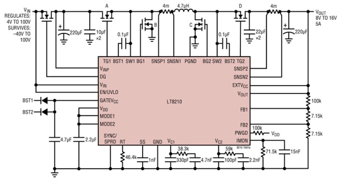
The answer is no, and that insight led to the design of the LT8210 family (Figure 1) of 100 volt input, synchronous, 4-switch, buck‑boost DC/DC controllers with their unique Pass-Thru feature.
 Figure 1: The suggested schematic of periphery components for the LT8210 family of 100 volt buck-boost switching controllers which offers multiple operating modes, including a unique Pass-Thru capability. (Image source: Analog Devices)
When you invoke this feature, the input passes directly to the output if the input is within a window, with hardwired thresholds that you set using simple resistors (Figure 1, right). In this non-switching state, there is no EMI. There are also no switching losses, thus enabling efficiencies up to 99.9%.
The buck or boost-regulation loops maintain the output at the set maximum or minimum values for input voltages above or below the Pass-Thru window. In addition, the LT8210 can operate as a conventional buck-boost controller with pin-selectable continuous conduction mode (CCM), pulse-skipping, or Burst Mode operation (Figure 1, left).
The Pass-Thru operation is clarified with a simplified schematic diagram of an LT8210 configured for that mode (Figure 2), with the output regulated to be between 8 and 16 volts. The top and bottom voltages of the window are set by resistive dividers FB2 and FB1, respectively.
 Figure 2: This simplified schematic diagram shows how the LT8210 can be set up in a Pass-Thru configuration with a regulated VOUT from 8 V and 16 V. (Image source: Analog Devices)
This circuit's input/output transfer characteristic shows that when the input voltage is above the Pass-Thru window setting, the LT8210 steps it down to a regulated 16 volt output (Figure 3). Alternatively, if the input voltage drops below the window setting, the LT8210 boosts it to maintain the output at 8 volts.
 Figure 3: Shown is the voltage input/output transfer function in Pass-Thru mode; the LT8210 manages the output voltage for input voltages above 16 volts and below 8 volts as well as those between the two threshold figures. (Image source: Analog Devices)
However, when the input voltage is within the window, the top-row FET switches (A and D) turn on continuously, allowing the output to simply track the input. At the same time, the LT8210 enters a low-power state with typical quiescent currents on the VIN and VINP pins of just 4 microamperes (μA) and 18 μA, respectively. In this non-switching state, no EMI is generated, nor are there switching losses, making almost 100% efficiency possible.
Let’s look at design scenarios where this wider output voltage window with reduced output regulation is technically acceptable:
• For loads such as the classic electromechanical relay, the driving voltage is often not critical and may have a relatively wide tolerance, such as ±5% or even ±10% of nominal.
• It can benefit applications where the voltage input from a battery may have wide swings, such as in automotive systems where the rail from a nominal 12 volt battery can range between engine cold crank (down to 3 volts) and load dump (up to 100 volts).
• Supplying DC rails with wider tolerances may also be acceptable in multistage power distribution topologies. Here, the output of the DC/DC controller or regulator function is not driving the final loads directly. Instead, it functions as an intermediate stage that drives one or more independent regulators to provide individual lower-voltage rails for the system.
Conclusion
Designers of DC/DC controllers and regulators usually focus on achieving tight output regulation, and with good reason. Nonetheless, out-of-the-box thinking takes advantage of the many situations where much looser regulation is acceptable, and this spurs innovative, unconventional approaches to improve performance. An example is the LT8210 with its Pass-Thru mode, which offers lower EMI and superior efficiency in certain input/output-voltage scenarios.
Related Content (DigiKey)
LT8210 Buck-Boost DC/DC Controllers with Pass-Through
https://www.digikey.com/en/product-highlight/l/linear-tech/lt8210-buck-boost-dc-dc-controller
Boost the Efficiency and Lower the Noise of DC Regulated Circuits
https://www.digikey.com/en/blog/boost-the-efficiency-and-lower-the-noise-of-dc-regulated-circuits
Use Low-EMI Switching Regulators to Optimize High-Efficiency Power Designs
https://www.digikey.com/en/articles/use-low-emi-switching-regulators-high-efficiency-power-designs
Related Content (Analog Devices)
4-Switch Buck-Boost Controller with Pass-Thru Capability Eliminates Switching Noise
Increase System Efficiency with ADI's Pass-Thru Technology (video)
https://www.analog.com/en/resources/media-center/videos/6352034761112.html

Have questions or comments? Continue the conversation on TechForum, Digi-Key's online community and technical resource.
Visit TechForum


