Mfr Part # 5700
QT PY ESP32-S3 2MB PSRAM
Adafruit Industries LLC
License: See Original Project LCD / TFT Solder / Desoldering
Courtesy of Adafruit
Guide by Ben Everard
Overview
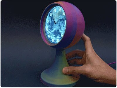
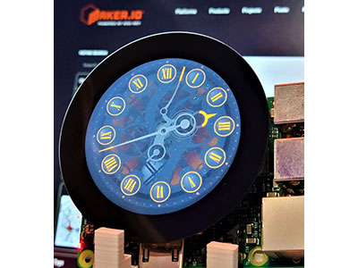
Create a world clock to show a satellite photo of the earth with the current midday at the center of the display. The map slowly scrolls across doing a complete loop every 24 hours.
This clock tracks solar time so the middle of the display is the point where the sun in highest in the sky. Solar time is usually quite close to the time our clocks show but doesn't take into account daylight savings or time zones that are ahead or behind solar time.
In the above photo, it's solar noon in England, so the time is 8am in New York and 5am in Los Angeles. Slightly confusingly, it's 1pm in London (because of daylight savings time).
Parts:
Adafruit QT Py S3 with 2MB PSRAM WiFi Dev Board with STEMMA QT
Adafruit EYESPI BFF for QT Py or Xiao - 18 Pin FPC Connector
You might also need:
You'll need something like the following to power and program your clock.
If you have access to a 3D printer, you can print out your support for the clock. Alternatively, you can fabricate a support out of whatever you like. It would be fairly straightforward to make one out of wood or foam board. The mounting points on the LCD take M2 machine screws (or other screws that will fit through a 0.1 inch hole).
Connecting the Hardware
The Adafruit EYESPI BFF for QT Py comes with header pins that you can use to solder this board to the Adafruit QT Py S3, but you need to break them into two segments each 7 pins long.
Before powering up your soldering iron, do a dry fit to ensure you know what you're connecting to where. Make sure that you've connected the two boards the right way around (the flex cable port and the USB C port should be at the same end and each be on the outside of the sandwich. You can confirm that everything's as it should be because the 5V and A0 pins should be against their equivalent number on both boards. The plastic part of the pins should be between the two boards preventing any components from touching.
Keep everything together like this and solder each pin to make the connection permanent. It should look like the image below.
Connect the Screen to the BFF
The EYESPI Cable connects the Adafruit 1.28" 240x240 Round TFT LCD Display to the Adafruit EYESPI BFF for QT Py. On both boards, there is a connector for flat cables. Gently lever up the darker plastic clip gently using your fingernail (or something similar) – it should rotate 90 degrees and expose some contact underneath. On either end of the cable there are exposed metal contacts. The metal contacts on one end of the cable should be placed on top of the metal contacts on the connector, then push the cable as far into the connector as it will go. Once in place, the dark plastic clip can be pressed back down to secure the cable. When it's connected properly, it should withstand a gentle tug – if it comes out, repeat the process being sure to push the cable as far into the connector as possible.
Repeat the process on the LCD side so that cable joins the Adafruit EYESPI BFF and the LCD.
That's the hardware connected, it's time to move onto the software.
CircuitPython
CircuitPython is a derivative of MicroPython designed to simplify experimentation and education on low-cost microcontrollers. It makes it easier than ever to get prototyping by requiring no upfront desktop software downloads. Simply copy and edit files on the CIRCUITPY drive to iterate.
CircuitPython QuickStart
Follow this step-by-step to quickly get CircuitPython running on your board.
There are two versions of this board: one with 8MB Flash/No PSRAM and one with 4MB Flash/2MB PSRAM. Each version has their own UF2 build for CircuitPython. There isn't an easy way to identify which version of the board you have by looking at the board silk. If you aren't sure which version you have, try either build to see which one works.
There are two versions of this board: one with 8MB Flash/No PSRAM and one with 4MB Flash/2MB PSRAM.
Click the link above to download the latest CircuitPython UF2 file.
Save it wherever is convenient for you.
Plug your board into your computer, using a known-good data-sync cable, directly, or via an adapter if needed.
Click the reset button once (highlighted in red above), and then click it again when you see the RGB status LED(s) (highlighted in green above) turn purple (approximately half a second later). Sometimes it helps to think of it as a "slow double-click" of the reset button.
If you do not see the LED turning purple, you will need to reinstall the UF2 bootloader. See the Factory Reset page in this guide for details.
On some very old versions of the UF2 bootloader, the status LED turns red instead of purple.
For this board, tap reset and wait for the LED to turn purple, and as soon as it turns purple, tap reset again. The second tap needs to happen while the LED is still purple.
Once successful, you will see the RGB status LED(s) turn green (highlighted in green above). If you see red, try another port, or if you're using an adapter or hub, try without the hub, or different adapter or hub.
If double-clicking doesn't work the first time, try again. Sometimes it can take a few tries to get the rhythm right!
A lot of people end up using charge-only USB cables and it is very frustrating! Make sure you have a USB cable you know is good for data sync.
If after several tries, and verifying your USB cable is data-ready, you still cannot get to the bootloader, it is possible that the bootloader is missing or damaged. Check out the Factory Reset page for details on resolving this issue.
You will see a new disk drive appear called QTPYS3BOOT.
Drag the adafruit_circuitpython_etc.uf2 file to QTPYS3BOOT.
The BOOT drive will disappear, and a new disk drive called CIRCUITPY will appear.
That's it!
Code
Are you new to using CircuitPython? No worries, there is a full getting started guide here.
Adafruit suggests using the Mu editor to edit your code and have an interactive REPL in CircuitPython. You can learn about Mu and installation in this tutorial.
Getting the image
The clock is going to display an image of the earth, so the first thing to do is get this image. NASA makes all their images free to use and has a full earth image made from multiple satellite photos stitched together. This has been converted into the right format and resized. The resulting image is available below. Save this image with the file name world.bmp to the root directory of your QT Py (depending on your browser, that probably means right click > Save Image As).
Set your environmental variables
The clock will get the current time from the internet, so it needs the details to log into your WiFi network. Open the settings.toml file on your QT Py (or create one if it doesn't already exist), and enter the following:
CIRCUITPY_WIFI_SSID = "YOUR-WIFI-SSID"
CIRCUITPY_WIFI_PASSWORD = "YOUR-WIFI-PASSWORD"
With the correct Wifi password and network name. Ensure the values on the right are in double quotes (")
Get the libraries and code
You'll need the following libraries.
adafruit_connection_manager.mpy
adafruit_gc9a01a.mpy
adafruit_ntp.mpy
The easiest way to get these is to click 'Download Project Bundle' below. This will give you a ZIP file containing the code and libraries you need for this project. Save this file somewhere on your computer and open it up. You should see folders for each of the current versions of CircuitPython. Take the code.py file and lib folder from the folder for your version of CircuitPython and copy them onto your QT Py.
# SPDX-FileCopyrightText: 2025 Ben Everard for Adafruit Industries
#
# SPDX-License-Identifier: MIT
'''Display a world clock on a round LCD'''

import os
import time
import board
import displayio
import fourwire
from adafruit_gc9a01a import GC9A01A
import wifi
import adafruit_ntp
import adafruit_connection_manager

wifi.radio.connect(ssid=os.getenv('CIRCUITPY_WIFI_SSID'),
                   password=os.getenv('CIRCUITPY_WIFI_PASSWORD'))

pool = adafruit_connection_manager.get_radio_socketpool(wifi.radio)
ntp = adafruit_ntp.NTP(pool, tz_offset=0, cache_seconds=3600)

displayio.release_displays()
spi = board.SPI()
tft_cs = board.TX
tft_dc = board.RX

display_bus = fourwire.FourWire(
    spi, command=tft_dc, chip_select=tft_cs, reset=None
)

display = GC9A01A(display_bus, width=240, height=240, auto_refresh=False)

world = displayio.OnDiskBitmap("/world.bmp")

tile_grid_1 = displayio.TileGrid(world, pixel_shader=world.pixel_shader)
tile_grid_2 = displayio.TileGrid(world, pixel_shader=world.pixel_shader)

group = displayio.Group()

group.append(tile_grid_1)
group.append(tile_grid_2)
display.root_group = group

# Loop forever so you can enjoy your image
while True:
    tile_grid_1.x = (20*ntp.datetime.tm_hour)+120
    tile_grid_2.x = tile_grid_1.x-480
    display.refresh()
    time.sleep(60)
As soon as this is all saved, the QT Py should reboot and after a few seconds, display an image of the world with the current mid-day point in the middle. If it doesn't then check that you have all the required files on the device, and that you are in an area with Wifi coverage.
Map projection
There is a bit of a rendering error in this clock. The Earth is obviously a sphere, and the image we're using is a flat rectangle. There are various ways of squishing an image of a sphere onto a rectangle, but they all introduce errors.
Our clock doesn't account for the curvature of the earth. To us, this doesn't matter because it makes it easier to recognize the part of the Earth that's currently showing. If you'd prefer to render it in a different way, you can update the code however you'd like.
That's the electronics setup. Now to look at the physical setup.
Finishing Touches
Our clock holder needs to fulfill two basic tasks:
Keep the clock face upright.
Stop the pins on the QT Py touching the back of the LCD.
As long as you manage those things, you can set it up however you like. There is an STL file you can use if you want to but be as creative as you like with your housing.
You can download the clock holder STL file from https://www.printables.com/model/1281120-clock-holder or via the green button below. It should print on its side without supports. Two machine screws hold the LCD in place. There are no mounting holes on the QT Py, so you'll need to use a dollop of something sticky to hold it in place. I used White Tack, but hot glue would also work (but might be harder to remove). Whatever you use, just be careful to keep it away from the USB or STEMMA QT ports.
Once everything's together, plug it into a power source and enjoy your world clock.