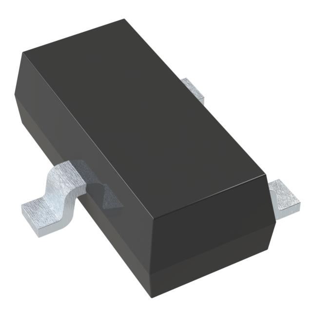
Mfr Part # SI2308BDS-T1-BE3
N-CHANNEL 60-V (D-S) MOSFET
Vishay Siliconix
License: Attribution Non-commercial Oscilloscope Serial / UART
What's going on with our "working" board?
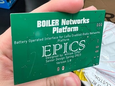
If you have been following along, last week I talked about data compression and how we successfully sent data to our base station in a compressed format. That was an exciting post because I thought that the device would be ready to connect to a solar panel and be put into the real world! Unfortunately, that is not how the week went. When we went to plug in the solar panel, we weren't getting any charge LEDs from the charge controller, so the system was running on only the battery. This of course is not ideal since once the battery dies we would have a completely useless sensor node sitting idle on a lamp post and weathering the environment without logging any of the data.
Obviously this is something we needed to fix and to do that we started with continuity tests and voltage measurements on the board.
The same PCB picture as before, but now we know somewhere here there is a problem.
The section of the board we were most focused on was the section in the lower left corner with the USB, screw terminal labeled "SOLAR" and the charge controller. Somewhere and for some reason, the charge LED was not lighting up, and it was time to figure out why.
The first step for solving this issue was to measure the continuity between the solar ground and the power system ground, once that was verified we measured and confirmed that the solar panel was indeed outputting 5V to the screw terminal and also to the test pad labeled "SOLAR." We know we are getting power onto the board now.
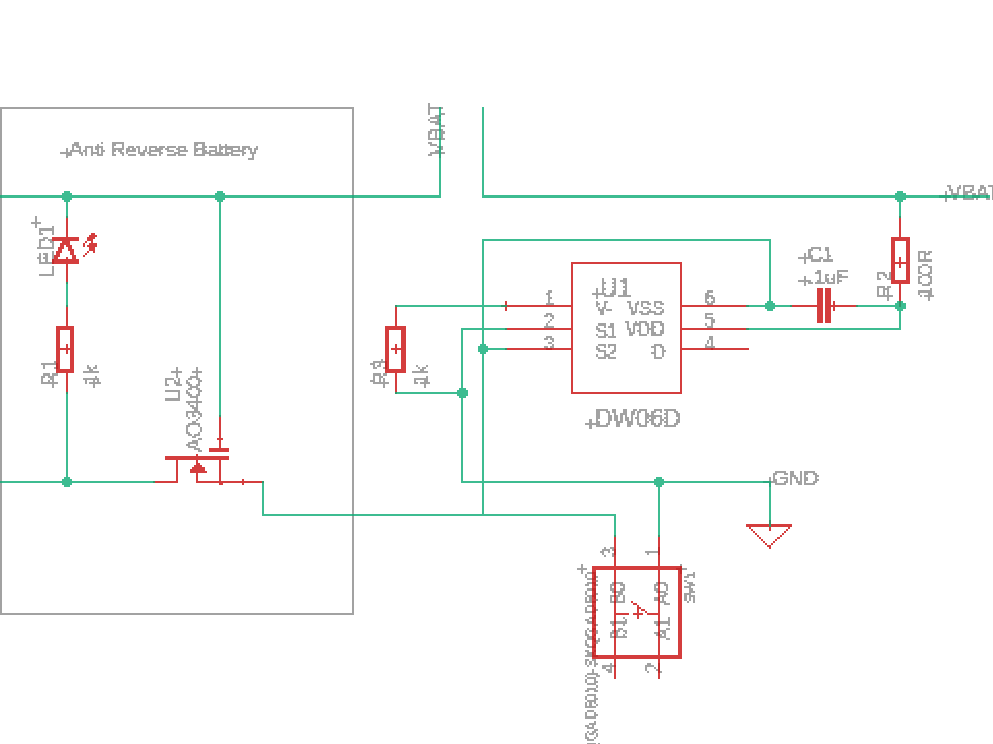
Next, we measured pin 4 of the charge controller and expected to see 5V based on the schematic here:
Charging Circuit
The key to this whole circuit is the SI2301 p-MOSFET that controls whether power is delivered from the USB or the Solar panel. With some careful measurements, we found that when there was no USB connected there was no connection between pin 3 and pin 2 of the MOSFET, which is not what was supposed to happen. Typically a p-MOSFET behaves as a normally closed circuit, so the solar should always be connected UNLESS the USB is connected and then the power to pin 1 would cause the switch to open and power to stop flowing from the solar panel and instead supply power to the charger from the USB.
I next plugged the USB in and measured the connection between pin 3 and pin 2. Sure enough, the connection was active and the root cause was found. We accidentally ordered an n-MOSFET instead of a p-MOSFET for our circuit. I linked both parts below, but I made a critical error when ordering the PCB by going too fast with component selection. I accidentally ordered the Vishay SI2308 which is the N-channel MOSFET when I needed the Vishay SI2301, which is the P-Channel Equivalent. Such a simple mistake but a great opportunity to learn a valuable lesson in PCB design: Always quadruple-check that you chose the right part numbers, and then check again.
At least your software works! Right?
Let me paint a picture for you. You're sitting on a lab bench and you see all of your hard work come together and the data you've been working on sending all semester finally sent and was successfully received. You tell everyone on the team, you schedule a test day to put the device outside, then you find out that your code only works when connected to a computer.
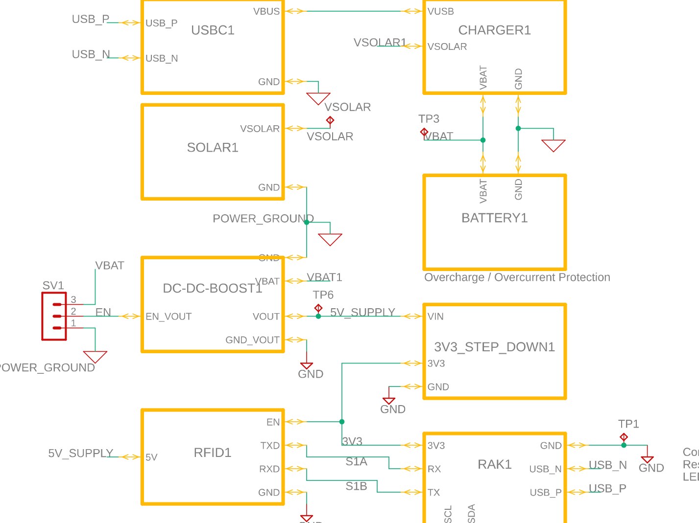
This is exactly what happened to me. You see, it seems that something is going on with the code where there is only valid serial communication to the RFID module when there is Serial communication to a computer. The only thing is, as you can see below, there is not a shared serial between RFID and USB...
Block Diagram of the System
As you can see, there is a completely different serial bus for the RAK module to RFID and from the RAK to USB. To be specific, Serial1 goes to the RFID module, and Serial0 goes to USB.
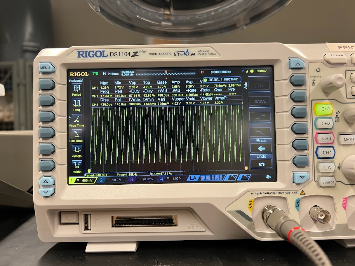
We are not yet sure what is going on, whether software or hardware, but we know that whatever the issue happens to be it was certainly our fault. We got a chance to notice something about the signal though, when the serial0 is connected, we are sending to the RFID the command to read a tag, and the RFID unit responds. When we disconnect and run on only the battery, we get the same sent signal, but the response stays at an Idle voltage. The picture below shows us measuring the signal with an oscilloscope and decoding it into hexidecimal. It was really fascinating to see the value decoded properly and see the circuit working in front of us in real time.
Serial Messages displayed on the Oscilloscope and Decoded
As a quick recap, we found the hardware issue on the board that was causing the solar panel to not work and it was because of the wrong component being ordered and placed onto the board. Unfortunately for us, the serial issue wasn't as simple, and we have not found the cause. When we do find the cause, it will for sure be in a blog post, but for now, that is all I have for this week.
I still really enjoy this project, and I have been enjoying it more now that there is an issue for me to solve. I really enjoy solving electrical issues because it makes me feel like I'm literally making magic.
This week I was able to reflect more on what it means to me to have these challenging learning experiences and how I hope to continue to grow from them. If you are interested in reading the reflection, I have attached it below. With that said, my name is Will Siffer, and as the Digi-Key Ambassador of Purdue University, I hope you stay curious.
Recommended Reading
Senior Design Part 4: Assembling, Testing, and Debugging Circuit Boards!
Senior Design Part 7: Compressing data with Magic? (It's just math!)
"This week we worked on debugging and trying to get the unit successfully mounted outside. Unfortunately for us there is a bug in the code that is causing Serial1 communication to not properly initialize and causing the RFID to not tell us when there is a tag present. This issue is particularly strange because the board works perfectly fine connected to the computer, but it doesn't work when it is on its own and not communicating over serial. This is leading to the first frustration of the project since it is causing us to not test on schedule. One benefit of this experience is that there is now a new issue for me to learn and overcome as it pertains to this project. I love working on issues because it forces me out of my comfort zone and learning something new. In this case, I am learning about serial communication and that is really interesting to me since I am likely to continue using serial communication in my personal projects. As I move past this class and into graduation, I am excited to be given new issues to solve so I can be exposed to more technologies and learn more about how various systems work."