Mfr Part # 3036
RGB MATRIX FEATHERWING KIT M0 M4
Adafruit Industries LLC
License: See Original Project
Courtesy of Adafruit
Guide by Jeff Epler, Phillip Burgess, Lady Ada, Melissa LeBlanc-Williams
Overview
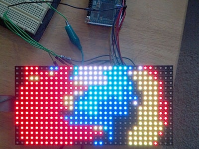
Bring a little bit of Times Square into your home with our RGB LED matrix panels. These panels are normally used to make video walls — here in New York we see them on the sides of buses and on bus stops — to display animations or short video clips. We thought they looked really cool, so we picked up a few boxes from the factory. They come in a variety of sizes from 16x32 pixels and up.
Using the new RGBMatrix library, CircuitPython can blast pixels to these displays really quickly. Use it with DisplayIO for showing text, bitmaps, animations, and more. Not familiar with DisplayIO? There's a guide for that.
This guide is for select CircuitPython boards — ones based on the SAMD51 (Feather M4, ItsyBitsy M4, Metro M4 etc) and nRF52840 (Feather nRF52840, ItsyBitsy nRF52840, etc).
We have a different guide for Raspberry Pi and Arduino.
CircuitPython and Arduino share the same basic code for driving these matrices. In CircuitPython, we call it RGBMatrix. In Arduino, it's named Protomatter.
These panels require 12 or 13 digital pins (6 bit data, 6 or 7 bit control) and a good 5V power supply, at least a couple amps per panel. We suggest our 2A (or larger) regulated 5V adapters and either a terminal block DC jack or solder a jack from our DC extension cord. Please read the rest of our tutorial for more details!
Keep in mind that these displays are normally designed to be driven by FPGAs or other high-speed processors; they do not have built in PWM control of any kind. Instead, you're supposed to redraw the screen over and over to 'manually' PWM the whole thing. RGBMatrix takes care of that for you, offering up to thousands of bright colors. Depending on settings (width, height, and color depth) and microcontroller, RGBMatrix takes from 10% to 60% of the processing power away from CircuitPython.
Of course, we wouldn't leave you with a datasheet and a "good luck!" We have a full wiring diagrams and working CircuitPython code.
Connecting with Feather M4 Express & FeatherWing
The easiest way to get started with RGBMatrix is with the RGB Matrix FeatherWing. Now you can quickly and easily create projects featuring your favorite 16 or 32-pixel tall matrix boards.
Please note: This wing is only tested/designed to work with the SAMD51 M4 Feather or the nRF52840 Feather. It may be possible to use the extra holes as a prototyping area to adapt it to other Feathers, but that's beyond the scope of this guide.
This wing can be assembled in one of two ways. You can either solder in a 2x8 IDC shrouded header on the top, then plug in the IDC cable that came with your matrix. This makes it easy to stack on top of your Feather. Or you can solder in the 2x10 socket header on the bottom of the Wing, and then stack your Feather on top. That way you can plug it directly into the back of the matrix *mind blown*.
This FeatherWing will work great with any of our 16x32, 32x32, or 64x32 RGB matrices, and is definitely the easiest way to glow and go.
Either way you decide to go, you can plug a 5V DC power pack into the 2.1mm DC jack. That 5V is polarity protected and then output on the other side to a 5.08mm terminal block. An onboard regulator will provide 3.3V power to your Feather, so you don't need a separate USB or battery. This makes for a very compact build!
Each 'Wing kit comes with one FeatherWing PCB with surface mount parts attached, a 2x8 IDC header, a 2x10 female socket, 2.1mm DC jack, 5.08mm terminal block, and some male header. You may also want some Feather stacking headers or female headers depending on how you plan to attach/stack your Feather.
Use the following block of code to initialize a 64x32 matrix.
displayio.release_displays()
matrix = rgbmatrix.RGBMatrix(
    width=64, bit_depth=4,
    rgb_pins=[board.D6, board.D5, board.D9, board.D11, board.D10, board.D12],
    addr_pins=[board.A5, board.A4, board.A3, board.A2],
    clock_pin=board.D13, latch_pin=board.D0, output_enable_pin=board.D1)
display = framebufferio.FramebufferDisplay(matrix)
Use the following block of code to initialize a 32x16 matrix. In this mode, you may not use pin A2 unless you cut the trace connecting it to the header, because it is connected to GND on the RGB matrix.
displayio.release_displays()
matrix = rgbmatrix.RGBMatrix(
    width=32, bit_depth=4,
    rgb_pins=[board.D6, board.D5, board.D9, board.D11, board.D10, board.D12],
    addr_pins=[board.A5, board.A4, board.A3],
    clock_pin=board.D13, latch_pin=board.D0, output_enable_pin=board.D1)
display = framebufferio.FramebufferDisplay(matrix)
Connecting with Feather RP2040 & FeatherWing
The easiest way to get started with RGBMatrix is with the RGB Matrix FeatherWing. Now you can quickly and easily create projects featuring your favorite 16 or 32-pixel tall matrix boards.
Please note: This wing is only tested/designed to work with the SAMD51 M4 Feather or the nRF52840 Feather. It may be possible to use the extra holes as a prototyping area to adapt it to other Feathers, but that's beyond the scope of this guide.
This wing can be assembled in one of two ways. You can either solder in a 2x8 IDC shrouded header on the top, then plug in the IDC cable that came with your matrix. This makes it easy to stack on top of your Feather. Or you can solder in the 2x10 socket header on the bottom of the Wing, and then stack your Feather on top. That way you can plug it directly into the back of the matrix *mind blown*.
This FeatherWing will work great with any of our 16x32, 32x32, or 64x32 RGB matrices, and is definitely the easiest way to glow and go.
Either way you decide to go, you can plug a 5V DC power pack into the 2.1mm DC jack. That 5V is polarity protected and then output on the other side to a 5.08mm terminal block. An onboard regulator will provide 3.3V power to your Feather, so you don't need a separate USB or battery. This makes for a very compact build!
Each 'Wing kit comes with one FeatherWing PCB with surface mount parts attached, a 2x8 IDC header, a 2x10 female socket, 2.1mm DC jack, 5.08mm terminal block, and some male header. You may also want some Feather stacking headers or female headers depending on how you plan to attach/stack your Feather.
Use the following block of code to initialize a 64x32 matrix.
displayio.release_displays()
matrix = rgbmatrix.RGBMatrix(
    width=64, bit_depth=4,
    rgb_pins=[board.D6, board.D5, board.D9, board.D11, board.D10, board.D12],
    addr_pins=[board.D25, board.D24, board.A3, board.A2],
    clock_pin=board.D13, latch_pin=board.D0, output_enable_pin=board.D1)
display = framebufferio.FramebufferDisplay(matrix)
Use the following block of code to initialize a 32x16 matrix. In this mode, you may not use pin A2 unless you cut the trace connecting it to the header, because it is connected to GND on the RGB matrix.
displayio.release_displays()
matrix = rgbmatrix.RGBMatrix(
    width=32, bit_depth=4,
    rgb_pins=[board.D6, board.D5, board.D9, board.D11, board.D10, board.D12],
    addr_pins=[board.D25, board.D24, board.A3],
    clock_pin=board.D13, latch_pin=board.D0, output_enable_pin=board.D1)
display = framebufferio.FramebufferDisplay(matrix)
With the RP2040, it is normal for the display to flicker while writing to the CIRCUITPY drive, such as when updating your code.py file. It will not harm the display.
Complete example: RP2040 Feather Scroller
Save the below file (called rp2040.py to CIRCUITPY as code.py and also save the bitmap image file pi-logo32b.bmp to CIRCUITPY. The 64x32 matrix will scroll the text "RP2040 Feather" over a Raspberry Pi logo.
# SPDX-FileCopyrightText: 2021 Jeff Epler for Adafruit Industries
#
# SPDX-License-Identifier: MIT

import time
from math import sin
import board
import displayio
import rgbmatrix
import framebufferio
import adafruit_imageload
import terminalio
from adafruit_display_text.label import Label

displayio.release_displays()
matrix = rgbmatrix.RGBMatrix(
    width=64, bit_depth=6,
    rgb_pins=[board.D6, board.D5, board.D9, board.D11, board.D10, board.D12],
    addr_pins=[board.D25, board.D24, board.A3, board.A2],
    clock_pin=board.D13, latch_pin=board.D0, output_enable_pin=board.D1,
    doublebuffer=True)
display = framebufferio.FramebufferDisplay(matrix, auto_refresh=False)

g = displayio.Group()
b, p = adafruit_imageload.load("pi-logo32b.bmp")
t = displayio.TileGrid(b, pixel_shader=p)
t.x = 20
g.append(t)

l = Label(text="Feather\nRP2040", font=terminalio.FONT, color=0xffffff, line_spacing=.7)
g.append(l)

display.show(g)

target_fps = 50
ft = 1/target_fps
now = t0 = time.monotonic_ns()
deadline = t0 + ft

p = 1
q = 17
while True:
    tm = (now - t0) * 1e-9
    x = l.x - 1
    if x < -40:
        x = 63
    y =  round(12 + sin(tm / p) * 6)
    l.x = x
    l.y = y
    display.refresh(target_frames_per_second=target_fps, minimum_frames_per_second=0)
    while True:
        now = time.monotonic_ns()
        if now > deadline:
            break
        time.sleep((deadline - now) * 1e-9)
deadline += ftConnecting Using a Proto Shield
Your LED matrix display needs 12 or 13 digital pins, and only specific combinations will work. If this much custom wiring worries you, choose the Feather M4 Express with an RGB Matrix Featherwing Kit, because just by connecting the headers you get everything in the right place!
If you hold a ribbon cable flat — no folds — and with both connectors facing you, keys pointed the same direction — there’s is a 1:1 correlation between the pins. The top-right pin on one plug links to the top-right on the other plug, and so forth. This holds true even if the cable has a doubled-over strain relief. As long as the keys point the same way and the plugs face the same way, pins are in the same positions at both ends.
Either end of the ribbon cable can be plugged into the matrix INPUT socket.
The free end of the ribbon can point toward the center of the matrix or hang off the side…the pinout is still the same. Notice below the direction of the “key” doesn’t change.
A dual-row header gets installed on the prototyping area, similar to the connector on the matrix. Just like the ribbon cable lying flat, as long as these two headers are aligned the same way, they’ll match pin-for-pin.
Wires are then soldered from the header to specific microcontroller pins. Try to keep wire lengths reasonably short to avoid signal interference.
Using color-coded wires helps a lot! If you don’t have colored wires, that’s okay, just pay close attention where everything goes. Our goal is a proto shield something like this (but this is just an example; refer to the following pages for specific information for your board):
You can also use a plain 2x8-pin male header, or two 1x8 sections installed side-by-side (as in the photo above). Since there’s no alignment key with this setup, you might want to indicate it with some tape or a permanent marker.
Depending on the make and model of proto shield, some pins are designed to connect in short rows. Others don’t. For the latter, strip a little extra insulation and bend the wire to wrap around the leg of the socket from behind, then solder.
Connect Ground Wires
32x32 and 64x32 matrices require three ground connections. 32x16 matrices have four.
Most proto shields have tons of grounding points, so you shouldn’t have trouble finding places to connect these.
Upper RGB Data
Pins R1, G1, and B1 (labeled R0, B0 and G0 on some matrices) deliver data to the top half of the display.
Lower RGB Data
Pins R2, G2, and B2 (labeled R1, G1 and B1 on some matrices) deliver data to the bottom half of the display.
Row Select Lines
Pins A, B, C, and D select which two rows of the display are currently lit. (32x16 matrices don’t have a “D” pin — it’s connected to ground instead.)
LAT Wire
The LAT (latch) signal marks the end of a row of data.
OE Wire
OE (output enable) switches the LEDs off when transitioning from one row to the next.
CLK Wire
Last one!
The CLK (clock) signal marks the arrival of each bit of data.
Want to use a breadboard? We've got you covered too. With the Breakout Helper, the 16-pin header can straddle that big gap in the middle.
Feather M4 Express
The easiest way to connect a LED matrix to the Feather M4 Express is using the RGB Matrix FeatherWing kit. This board works only with the Feather M4 Express, not other Feather boards like the nRF Feathers. If you've got the FeatherWing, jump over to this page. Otherwise, read on and get wiring!
To hook an LED matrix to the Feather M4 Express, make the connections on the left. Remember that for a 16-line matrix, connect 4 GND wires and address wires A, B, and C. For a 32-line matrix, connect 3 GND wires and address wires A, B, C, and D.
Use the following block of code to initialize a 64x32 matrix. Remember to connect all 4 address pins: A, B, C, and D.
Don't forget you have to provide a separate 5V @ 2 ~ 10Amp power supply to the panels thick power cables.
displayio.release_displays()
matrix = rgbmatrix.RGBMatrix(
    width=64, bit_depth=4,
    rgb_pins=[board.D6, board.D5, board.D9, board.D11, board.D10, board.D12],
    addr_pins=[board.A5, board.A4, board.A3, board.A2],
    clock_pin=board.D13, latch_pin=board.D0, output_enable_pin=board.D1)
display = framebufferio.FramebufferDisplay(matrix)
Use the following block of code to initialize a 32x16 matrix. Remember to connect just 3 address pins: A, B, and C. Hook a fourth GND wire instead of A3.
displayio.release_displays()
matrix = rgbmatrix.RGBMatrix(
    width=32, bit_depth=4,
    rgb_pins=[board.D6, board.D5, board.D9, board.D11, board.D10, board.D12],
    addr_pins=[board.A5, board.A4, board.A3],
    clock_pin=board.D13, latch_pin=board.D0, output_enable_pin=board.D1)
display = framebufferio.FramebufferDisplay(matrix)
Feather nRF52840
This suggested pinout was revised on 2020-06-03.
To hook an LED matrix to the Feather nRF52840 Express or Sense, make the connections on the left. Remember that for a 16-line matrix, connect 4 GND wires and address wires A, B, and C. For a 32-line matrix, connect 3 GND wires, and address wires A, B, C, and D.
Use the following block of code to initialize a 64x32 matrix. Remember to connect all 4 address pins: A, B, C, and D.
Don't forget you have to provide a separate 5V @ 2 ~ 10Amp power supply to the panels thick power cables.
displayio.release_displays()
matrix = rgbmatrix.RGBMatrix(
    width=64, bit_depth=4,
    rgb_pins=[board.D6, board.A5, board.A1, board.A0, board.A4, board.D11],
    addr_pins=[board.D10, board.D5, board.D13, board.D9],
    clock_pin=board.D12, latch_pin=board.RX, output_enable_pin=board.TX)
display = framebufferio.FramebufferDisplay(matrix)
Use the following block of code to initialize a 32x16 matrix. Remember to connect just 3 address pins: A, B, and C. Hook a fourth GND wire instead of A3.
displayio.release_displays()
matrix = rgbmatrix.RGBMatrix(
    width=32, bit_depth=4,
    rgb_pins=[board.D6, board.A5, board.A1, board.A0, board.A4, board.D11],
    addr_pins=[board.D10, board.D5, board.D13],
    clock_pin=board.D12, latch_pin=board.RX, output_enable_pin=board.TX)
display = framebufferio.FramebufferDisplay(matrix)
ItsyBitsy M4
To hook an LED matrix to the ItsyBitsy M4, make the connections on the left. Remember that for a 16-line matrix, connect 4 GND wires and address wires A, B, and C. For a 32-line matrix, connect 3 GND wires and address wires A, B, C, and D.
Use the following block of code to initialize a 64x32 matrix. Remember to connect all 4 address pins: A, B, C, and D.
Don't forget you have to provide a separate 5V @ 2 ~ 10Amp power supply to the panels thick power cables.
displayio.release_displays()
matrix = rgbmatrix.RGBMatrix(
    width=64, bit_depth=4,
    rgb_pins=[board.MOSI, board.SCK, board.A5, board.A4, board.A0, board.A1],
    addr_pins=[board.D5, board.D7, board.D9, board.D10],
    clock_pin=board.D13, latch_pin=board.D12, output_enable_pin=board.D11)
display = framebufferio.FramebufferDisplay(matrix)
Use the following block of code to initialize a 32x16 matrix. Remember to connect just 3 address pins: A, B, and C. Hook a fourth GND wire instead of A3.
displayio.release_displays()
matrix = rgbmatrix.RGBMatrix(
    width=32, bit_depth=4,
    rgb_pins=[board.MOSI, board.SCK, board.A5, board.A4, board.A0, board.A1],
    addr_pins=[board.D5, board.D7, board.D9],
    clock_pin=board.D13, latch_pin=board.D12, output_enable_pin=board.D11)
display = framebufferio.FramebufferDisplay(matrix)
ItsyBitsy nRF52840
To hook an LED matrix to the ItsyBitsy nRF52840, make the connections on the left. Remember that for a 16-line matrix, connect 4 GND wires and address wires A, B, and C. For a 32-line matrix, connect 3 GND wires and address wires A, B, C, and D.
Use the following block of code to initialize a 64x32 matrix. Remember to connect all 4 address pins: A, B, C, and D.
Don't forget you have to provide a separate 5V @ 2 ~ 10Amp power supply to the panels thick power cables.
displayio.release_displays()
matrix = rgbmatrix.RGBMatrix(
    width=64, bit_depth=4,
    rgb_pins=[board.A3, board.A2, board.A1, board.RX, board.TX, board.D5],
    addr_pins=[board.D7, board.D9, board.D10, board.D12],
    clock_pin=board.D2, latch_pin=board.D11, output_enable_pin=board.MISO)
display = framebufferio.FramebufferDisplay(matrix)
Use the following block of code to initialize a 32x16 matrix. Remember to connect just 3 address pins: A, B, and C. Hook a fourth GND wire instead of A3.
displayio.release_displays()
matrix = rgbmatrix.RGBMatrix(
    width=32, bit_depth=4,
    rgb_pins=[board.A3, board.A2, board.A1, board.RX, board.TX, board.D5],
    addr_pins=[board.D7, board.D9, board.D10],
    clock_pin=board.D2, latch_pin=board.D11, output_enable_pin=board.MISO)
display = framebufferio.FramebufferDisplay(matrix)
Metro M4 Express
To hook an LED matrix to the Metro M4 Express or Metro M4 Airlift Lite, make the connections on the left. Remember that for a 16-line matrix, connect 4 GND wires and address wires A, B, and C. For a 32-line matrix, connect 3 GND wires and address wires A, B, C, and D.
Use the following block of code to initialize a 64x32 matrix. Remember to connect all 4 address pins: A, B, C, and D.
Don't forget you have to provide a separate 5V @ 2 ~ 10Amp power supply to the panels thick power cables.
displayio.release_displays()
matrix = rgbmatrix.RGBMatrix(
    width=64, bit_depth=4,
    rgb_pins=[board.D8, board.D9, board.D10, board.D11, board.D12, board.D13],
    addr_pins=[board.D4, board.D5, board.D6, board.D7],
    clock_pin=board.D1, latch_pin=board.D3, output_enable_pin=board.D2)
display = framebufferio.FramebufferDisplay(matrix)
Use the following block of code to initialize a 32x16 matrix. Remember to connect just 3 address pins: A, B, and C. Hook a fourth GND wire instead of A3.
displayio.release_displays()
matrix = rgbmatrix.RGBMatrix(
    width=32, bit_depth=4,
    rgb_pins=[board.D8, board.D9, board.D10, board.D11, board.D12, board.D13],
    addr_pins=[board.D4, board.D5, board.D6],
    clock_pin=board.D1, latch_pin=board.D3, output_enable_pin=board.D2)
display = framebufferio.FramebufferDisplay(matrix)
Shields Up
If you're using the RGB Matrix Shield with the Metro M4 Express, you will need to make a hardware modification.
The RGB Matrix Shield is designed so that you can customize it to the requirements of your board. We need to change which pin is used for the "CLK" (clock) signal.
There is a small copper trace between the two larger pads. Using a razor blade, cut or scrape away this trace. (Young people, please have an adult do this step!) Then, use your multimeter in continuity mode to verify that there is no connection between the two rectangular pads.
Next, make a connection from the A4 pin to the CLK pin by soldering in a new wire as shown. The wire can be on the top or on the bottom.
Once that's done, use the following block of code to initialize a 64x32 matrix:
matrix = rgbmatrix.RGBMatrix(
    width=64,
    height=32,
    bit_depth=1,
    rgb_pins=[board.D2, board.D3, board.D4, board.D5, board.D6, board.D7],
    addr_pins=[board.A0, board.A1, board.A2, board.A3],
    clock_pin=board.A4,
    latch_pin=board.D10,
    output_enable_pin=board.D9,
)
Use the following block of code to initialize a 32x16 matrix:
matrix = rgbmatrix.RGBMatrix(
    width=32,
    height=16,
    bit_depth=1,
    rgb_pins=[board.D2, board.D3, board.D4, board.D5, board.D6, board.D7],
    addr_pins=[board.A0, board.A1, board.A2],
    clock_pin=board.A4,
    latch_pin=board.D10,
    output_enable_pin=board.D9,
)
Feather STM32F405
Support for this Feather is experimental, and you need to use CircuitPython 6.0.0-beta.3 or newer! If you get an ImportError, make sure you're using the right version.
To hook an LED matrix to the Feather STM32F405, make the connections on the left. Remember that for a 16-line matrix, connect 4 GND wires and address wires A, B, and C. For a 32-line matrix, connect 3 GND wires and address wires A, B, C, and D.
Use the following block of code to initialize a 64x32 matrix. Remember to connect all 4 address pins: A, B, C, and D.
Don't forget you have to provide a separate 5V @ 2 ~ 10Amp power supply to the panels thick power cables.
displayio.release_displays()
matrix = rgbmatrix.RGBMatrix(
    width=64, bit_depth=4,
    rgb_pins=[board.D13, board.D12, board.D11, board.A4, board.A5, board.D6],
    addr_pins=[board.A0, board.A1, board.A2, board.A3],
    clock_pin=board.D5, latch_pin=board.D9, output_enable_pin=board.D10)
display = framebufferio.FramebufferDisplay(matrix)
Use the following block of code to initialize a 32x16 matrix. Remember to connect just 3 address pins: A, B, and C. Hook a fourth GND wire instead of A3.
displayio.release_displays()
matrix = rgbmatrix.RGBMatrix(
    width=32, bit_depth=4,
    rgb_pins=[board.D13, board.D12, board.D11, board.A4, board.A5, board.D6],
    addr_pins=[board.A0, board.A1, board.A2],
    clock_pin=board.D5, latch_pin=board.D9, output_enable_pin=board.D10)
display = framebufferio.FramebufferDisplay(matrix)
Metro ESP32S2
A great way to get started with RGBMatrix is with the RGB Matrix Shield and the Metro ESP32-S2. Now you can quickly and easily create projects featuring your favorite 16 or 32-pixel tall matrix boards.
For a small panel, you can use the screw terminals on the Adafruit RGB Matrix Shield together with an appropriate DC power adapter on the Metro. For a larger panel, you'll need an independent 5V supply at several amps.
In any case, using USB power alone is not recommended, as the RGB Matrix can draw a lot of current.
Each Shield kit comes with one Shield PCB, a 2x8 IDC header, 5.08mm terminal block, and some male header.
Use the following block of code to initialize a 64x32 matrix.
displayio.release_displays()
matrix = rgbmatrix.RGBMatrix(
    width=32,
    bit_depth=6,
    rgb_pins=[board.IO7, board.IO8, board.IO9, board.IO10, board.IO11, board.IO12],
    addr_pins=[board.A0, board.A1, board.A2, board.A3],
    clock_pin=board.IO13,
    latch_pin=board.IO15,
    output_enable_pin=board.IO14,
)
display = framebufferio.FramebufferDisplay(matrix)
Use the following block of code to initialize a 32x16 matrix. In this mode, you may not use pin A3 unless you cut the trace connecting it to the header, because it is connected to GND on the RGB matrix.
displayio.release_displays()
matrix = rgbmatrix.RGBMatrix(
    width=32,
    bit_depth=4,
    rgb_pins=[board.IO7, board.IO8, board.IO9, board.IO10, board.IO11, board.IO12],
    addr_pins=[board.A0, board.A1, board.A2],
    clock_pin=board.IO13,
    latch_pin=board.IO15,
    output_enable_pin=board.IO14,
)
display = framebufferio.FramebufferDisplay(matrix)
Connecting Using a MatrixPortal
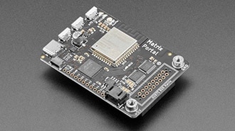
To hook an LED matrix to the MatrixPortal M4 board, just connect the power wires and press it on. Check out the Prep the MatrixPortal page for more detailed information. You can learn more about using the MatrixPortal in our Adafruit MatrixPortal M4 guide.
64x32 Matrix
Use the following block of code to initialize a 64x32 matrix.
displayio.release_displays()
matrix = rgbmatrix.RGBMatrix(
    width=64, bit_depth=4,
    rgb_pins=[
        board.MTX_R1,
        board.MTX_G1,
        board.MTX_B1,
        board.MTX_R2,
        board.MTX_G2,
        board.MTX_B2
    ],
    addr_pins=[
        board.MTX_ADDRA,
        board.MTX_ADDRB,
        board.MTX_ADDRC,
        board.MTX_ADDRD
    ],
    clock_pin=board.MTX_CLK,
    latch_pin=board.MTX_LAT,
    output_enable_pin=board.MTX_OE
)
display = framebufferio.FramebufferDisplay(matrix)32x16 Matrix
Use the following block of code to initialize a 32x16 matrix.
displayio.release_displays()
matrix = rgbmatrix.RGBMatrix(
    width=32, bit_depth=4,
    rgb_pins=[
        board.MTX_R1,
        board.MTX_G1,
        board.MTX_B1,
        board.MTX_R2,
        board.MTX_G2,
        board.MTX_B2
    ],
    addr_pins=[
        board.MTX_ADDRA,
        board.MTX_ADDRB,
        board.MTX_ADDRC
    ],
    clock_pin=board.MTX_CLK,
    latch_pin=board.MTX_LAT,
    output_enable_pin=board.MTX_OE
)
display = framebufferio.FramebufferDisplay(matrix)64x64 Matrix
Use the following block of code to initialize a 64x64 matrix. Don't forget to close the Address E Line jumper with solder. You'll need to check the datasheet for your matrix to determine whether to connect it to Pin 8 or 16.
Don't forget to close the Address E Line jumper first.
displayio.release_displays()
matrix = rgbmatrix.RGBMatrix(
    width=64, height=64, bit_depth=4,
    rgb_pins=[
        board.MTX_R1,
        board.MTX_G1,
        board.MTX_B1,
        board.MTX_R2,
        board.MTX_G2,
        board.MTX_B2
    ],
    addr_pins=[
        board.MTX_ADDRA,
        board.MTX_ADDRB,
        board.MTX_ADDRC,
        board.MTX_ADDRD,
        board.MTX_ADDRE
    ],
    clock_pin=board.MTX_CLK,
    latch_pin=board.MTX_LAT,
    output_enable_pin=board.MTX_OE
)
display = framebufferio.FramebufferDisplay(matrix)
Prep the MatrixPortal
Power Prep
The MatrixPortal supplies power to the matrix display panel via two standoffs. These come with protective tape applied (part of our manufacturing process) which MUST BE REMOVED!
Use some tweezers or a fingernail to remove the two amber circles.
Power Terminals
Next, screw in the spade connectors to the corresponding standoff.
red wire goes to +5V
black wire goes to GND
Panel Power
Plug either one of the four-conductor power plugs into the power connector pins on the panel. The plug can only go in one way, and that way is marked on the board's silkscreen.
Board Connection
Now, plug the board into the left side shrouded 8x2 connector as shown. The orientation matters, so take a moment to confirm that the white indicator arrow on the matrix panel is oriented pointing up and right as seen here and the MatrixPortal overhangs the edge of the panel when connected. This allows you to use the edge buttons from the front side.
Check nothing is impeding the board from plugging in firmly. If there's a plastic nub on the matrix that's keeping the Portal from sitting flat, cut it off with diagonal cutters.
For info on adding LED diffusion acrylic, see the page LED Matrix Diffuser.
Example: Simple two-line text scroller
This example creates two lines of scrolling text on a 64x32 matrix using CircuitPython Display Text. It's designed for the FeatherWing M4 Express, but you can adapt it to other boards by changing the lines that create the RGBMatrix object. We've thoroughly commented this example so it's a great place to start if you're not familiar with displayio.
For this example, make sure to install the following library:
CircuitPython Display Text - for displaying text
If you want to customize the example to use a different font, you'll also need
CircuitPython Bitmap Font Library - for bitmap font support
Here's how the code will work:
Create the RGBMatrix and FramebufferDisplay objects
Create the two text labels to scroll
Put them in a Group, and then show that Group
Repeatedly scroll each label to the left, returning it to the far-right hand side when it has gone all the way
# SPDX-FileCopyrightText: 2020 Jeff Epler for Adafruit Industries
#
# SPDX-License-Identifier: MIT

# This example implements a simple two line scroller using
# Adafruit_CircuitPython_Display_Text. Each line has its own color
# and it is possible to modify the example to use other fonts and non-standard
# characters.

import adafruit_display_text.label
import board
import displayio
import framebufferio
import rgbmatrix
import terminalio

# If there was a display before (protomatter, LCD, or E-paper), release it so
# we can create ours
displayio.release_displays()

# This next call creates the RGB Matrix object itself. It has the given width
# and height. bit_depth can range from 1 to 6; higher numbers allow more color
# shades to be displayed, but increase memory usage and slow down your Python
# code. If you just want to show primary colors plus black and white, use 1.
# Otherwise, try 3, 4 and 5 to see which effect you like best.
#
# These lines are for the Feather M4 Express. If you're using a different board,
# check the guide to find the pins and wiring diagrams for your board.
# If you have a matrix with a different width or height, change that too.
# If you have a 16x32 display, try with just a single line of text.
matrix = rgbmatrix.RGBMatrix(
    width=64, height=32, bit_depth=1,
    rgb_pins=[board.D6, board.D5, board.D9, board.D11, board.D10, board.D12],
    addr_pins=[board.A5, board.A4, board.A3, board.A2],
    clock_pin=board.D13, latch_pin=board.D0, output_enable_pin=board.D1)

# Associate the RGB matrix with a Display so that we can use displayio features
display = framebufferio.FramebufferDisplay(matrix, auto_refresh=False)

# Create two lines of text to scroll. Besides changing the text, you can also
# customize the color and font (using Adafruit_CircuitPython_Bitmap_Font).
# To keep this demo simple, we just used the built-in font.
# The Y coordinates of the two lines were chosen so that they looked good
# but if you change the font you might find that other values work better.
line1 = adafruit_display_text.label.Label(
    terminalio.FONT,
    color=0xff0000,
    text="This scroller is brought to you by CircuitPython RGBMatrix")
line1.x = display.width
line1.y = 8

line2 = adafruit_display_text.label.Label(
    terminalio.FONT,
    color=0x0080ff,
    text="Hello to all CircuitPython contributors worldwide <3")
line2.x = display.width
line2.y = 24

# Put each line of text into a Group, then show that group.
g = displayio.Group()
g.append(line1)
g.append(line2)
display.show(g)

# This function will scoot one label a pixel to the left and send it back to
# the far right if it's gone all the way off screen. This goes in a function
# because we'll do exactly the same thing with line1 and line2 below.
def scroll(line):
    line.x = line.x - 1
    line_width = line.bounding_box[2]
    if line.x < -line_width:
        line.x = display.width

# This function scrolls lines backwards.  Try switching which function is
# called for line2 below!
def reverse_scroll(line):
    line.x = line.x + 1
    line_width = line.bounding_box[2]
    if line.x >= display.width:
        line.x = -line_width

# You can add more effects in this loop. For instance, maybe you want to set the
# color of each label to a different value.
while True:
    scroll(line1)
    scroll(line2)
    #reverse_scroll(line2)
display.refresh(minimum_frames_per_second=0)Example: Two-line colorful text scroller
This example creates two lines of scrolling text on a 64x32 matrix. It's designed for the FeatherWing M4 Express, but you can adapt it to other boards by changing the lines that create the RGBMatrix object.
Because each letter is set to a different color, this example doesn't use the adafruit_display_text library.
To customize the text, simply make sure you keep the lines in pairs of equal length, and don't miss the comma at the end of each line.
# SPDX-FileCopyrightText: 2020 Jeff Epler for Adafruit Industries
#
# SPDX-License-Identifier: MIT

# This example implements a rainbow colored scroller, in which each letter
# has a different color. This is not possible with
# Adafruit_Circuitpython_Display_Text, where each letter in a label has the
# same color
#
# This demo also supports only ASCII characters and the built-in font.
# See the simple_scroller example for one that supports alternative fonts
# and characters, but only has a single color per label.

import array

from rainbowio import colorwheel
import board
import displayio
import framebufferio
import rgbmatrix
import terminalio
displayio.release_displays()

matrix = rgbmatrix.RGBMatrix(
    width=64, height=32, bit_depth=3,
    rgb_pins=[board.D6, board.D5, board.D9, board.D11, board.D10, board.D12],
    addr_pins=[board.A5, board.A4, board.A3, board.A2],
    clock_pin=board.D13, latch_pin=board.D0, output_enable_pin=board.D1)
display = framebufferio.FramebufferDisplay(matrix, auto_refresh=False)

# Create a tilegrid with a bunch of common settings
def tilegrid(palette):
    return displayio.TileGrid(
        bitmap=terminalio.FONT.bitmap, pixel_shader=palette,
        width=1, height=1, tile_width=6, tile_height=14, default_tile=32)

g = displayio.Group()

# We only use the built in font which we treat as being 7x14 pixels
linelen = (64//7)+2

# prepare the main groups
l1 = displayio.Group()
l2 = displayio.Group()
g.append(l1)
g.append(l2)
display.show(g)

l1.y = 1
l2.y = 16

# Prepare the palettes and the individual characters' tiles
sh = [displayio.Palette(2) for _ in range(linelen)]
tg1 = [tilegrid(shi) for shi in sh]
tg2 = [tilegrid(shi) for shi in sh]

# Prepare a fast map from byte values to
charmap = array.array('b', [terminalio.FONT.get_glyph(32).tile_index]) * 256
for ch in range(256):
    glyph = terminalio.FONT.get_glyph(ch)
    if glyph is not None:
        charmap[ch] = glyph.tile_index

# Set the X coordinates of each character in label 1, and add it to its group
for idx, gi in enumerate(tg1):
    gi.x = 7 * idx
    l1.append(gi)

# Set the X coordinates of each character in label 2, and add it to its group
for idx, gi in enumerate(tg2):
    gi.x = 7 * idx
    l2.append(gi)

#  These pairs of lines should be the same length
lines = [
    b"This scroller is brought to you by    CircuitPython & PROTOMATTER",
    b"        .... . .-.. .-.. --- / .--. .-. --- - --- -- .- - - . .-.",
    b"Greetz to ...          @PaintYourDragon      @v923z  @adafruit         ",
    b"  @danh        @ladyada  @kattni      @tannewt    all showers & tellers",
    b"New York Strong                       Wash Your Hands                  ",
    b"                  Flatten the curve                   Stronger Together",
]

even_lines = lines[0::2]
odd_lines = lines[1::2]

# Scroll a top text and a bottom text
def scroll(t, b):
    # Add spaces to the start and end of each label so that it goes from
    # the far right all the way off the left
    sp = b' ' * linelen
    t = sp + t + sp
    b = sp + b + sp
    maxlen = max(len(t), len(b))
    # For each whole character position...
    for i in range(maxlen-linelen):
        # Set the letter displayed at each position, and its color
        for j in range(linelen):
            sh[j][1] = colorwheel(3 * (2*i+j))
            tg1[j][0] = charmap[t[i+j]]
            tg2[j][0] = charmap[b[i+j]]
        # And then for each pixel position, move the two labels
        # and then refresh the display.
        for j in range(7):
            l1.x = -j
            l2.x = -j
            display.refresh(minimum_frames_per_second=0)

# Repeatedly scroll all the pairs of lines
while True:
    for e, o in zip(even_lines, odd_lines):
scroll(e, o)Example: (Ada)Fruit Machine
This example simulates a "fruit machine", similar to a slot machine, using emoji from the Adafruit Discord server. It's designed for the FeatherWing M4 Express, but you can adapt it to other boards by changing the lines that create the RGBMatrix object. The code is also designed for the 64x32 LED displays.
You'll also need the emoji.bmp file on your CIRCUITPY drive.
# SPDX-FileCopyrightText: 2020 Jeff Epler for Adafruit Industries
#
# SPDX-License-Identifier: MIT

import random
import time

import board
import displayio
import framebufferio
import rgbmatrix

displayio.release_displays()

matrix = rgbmatrix.RGBMatrix(
    width=64, height=32, bit_depth=3,
    rgb_pins=[board.D6, board.D5, board.D9, board.D11, board.D10, board.D12],
    addr_pins=[board.A5, board.A4, board.A3, board.A2],
    clock_pin=board.D13, latch_pin=board.D0, output_enable_pin=board.D1)
display = framebufferio.FramebufferDisplay(matrix, auto_refresh=False)

# This bitmap contains the emoji we're going to use. It is assumed
# to contain 20 icons, each 20x24 pixels. This fits nicely on the 64x32
# RGB matrix display.

filename = "emoji.bmp"

# CircuitPython 6 & 7 compatible
bitmap_file = open(filename, 'rb')
bitmap = displayio.OnDiskBitmap(bitmap_file)
pixel_shader = getattr(bitmap, 'pixel_shader', displayio.ColorConverter())

# # CircuitPython 7+ compatible
# bitmap = displayio.OnDiskBitmap(filename)
# pixel_shader = bitmap.pixel_shader

# Each wheel can be in one of three states:
STOPPED, RUNNING, BRAKING = range(3)

# Return a duplicate of the input list in a random (shuffled) order.
def shuffled(seq):
    return sorted(seq, key=lambda _: random.random())

# The Wheel class manages the state of one wheel. "pos" is a position in
# scaled integer coordinates, with one revolution being 7680 positions
# and 1 pixel being 16 positions. The wheel also has a velocity (in positions
# per tick) and a state (one of the above constants)
class Wheel(displayio.TileGrid):
    def __init__(self):
        # Portions of up to 3 tiles are visible.
        super().__init__(bitmap=bitmap, pixel_shader=pixel_shader,
                         width=1, height=3, tile_width=20, tile_height=24)
        self.order = shuffled(range(20))
        self.state = STOPPED
        self.pos = 0
        self.vel = 0
        self.y = 0
        self.x = 0
        self.stop_time = time.monotonic_ns()

    def step(self):
        # Update each wheel for one time step
        if self.state == RUNNING:
            # Slowly lose speed when running, but go at least speed 64
            self.vel = max(self.vel * 9 // 10, 64)
            if time.monotonic_ns() > self.stop_time:
                self.state = BRAKING
        elif self.state == BRAKING:
            # More quickly lose speed when braking, down to speed 7
            self.vel = max(self.vel * 85 // 100, 7)

        # Advance the wheel according to the velocity, and wrap it around
        # after 7680 positions
        self.pos = (self.pos + self.vel) % 7680

        # Compute the rounded Y coordinate
        yy = round(self.pos / 16)
        # Compute the offset of the tile (tiles are 24 pixels tall)
        yyy = yy % 24
        # Find out which tile is the top tile
        off = yy // 24

        # If we're braking and a tile is close to midscreen,
        # then stop and make sure that tile is exactly centered
        if self.state == BRAKING and self.vel == 7 and yyy < 4:
            self.pos = off * 24 * 16
            self.vel = 0
            self.state = STOPPED

        # Move the displayed tiles to the correct height and make sure the
        # correct tiles are displayed.
        self.y = yyy - 20
        for i in range(3):
            self[i] = self.order[(19 - i + off) % 20]

    # Set the wheel running again, using a slight bit of randomness.
    # The 'i' value makes sure the first wheel brakes first, the second
    # brakes second, and the third brakes third.
    def kick(self, i):
        self.state = RUNNING
        self.vel = random.randint(256, 320)
        self.stop_time = time.monotonic_ns() + 3_000_000_000 + i * 350_000_000

# Our fruit machine has 3 wheels, let's create them with a correct horizontal
# (x) offset and arbitrary vertical (y) offset.
g = displayio.Group()
wheels = []
for idx in range(3):
    wheel = Wheel()
    wheel.x = idx * 22
    wheel.y = -20
    g.append(wheel)
    wheels.append(wheel)
display.show(g)

# Make a unique order of the emoji on each wheel
orders = [shuffled(range(20)), shuffled(range(20)), shuffled(range(20))]

# And put up some images to start with
for si, oi in zip(wheels, orders):
    for idx in range(3):
        si[idx] = oi[idx]

# We want a way to check if all the wheels are stopped
def all_stopped():
    return all(si.state == STOPPED for si in wheels)

# To start with, though, they're all in motion
for idx, si in enumerate(wheels):
    si.kick(idx)

# Here's the main loop
while True:
    # Refresh the display (doing this manually ensures the wheels move
    # together, not at different times)
    display.refresh(minimum_frames_per_second=0)
    if all_stopped():
        # Once everything comes to a stop, wait a little bit and then
        # start everything over again.  Maybe you want to check if the
        # combination is a "winner" and add a light show or something.
        for idx in range(100):
            display.refresh(minimum_frames_per_second=0)
        for idx, si in enumerate(wheels):
            si.kick(idx)

    # Otherwise, let the wheels keep spinning...
    for idx, si in enumerate(wheels):
si.step()Example: Conway's "Game of Life"
According to Wikipedia, "John Horton Conway was an English mathematician active in the theory of finite groups, knot theory, number theory, combinatorial game theory, and coding theory. He also made contributions to many branches of recreational mathematics, most notably the invention of the cellular automaton called the Game of Life."
Web comic XKCD memorialized his passing with a comic which showed a stick person turning into a "glider", a construct in the Game of Life which will continue moving indefinitely into empty space.
This example opens with a recreation of XKCD's tribute to Conway, then from time to time refreshes the display with a random state. It's designed for the FeatherWing M4 Express, but you can adapt it to other boards by changing the lines that create the RGBMatrix object. The code is also designed for the 64x32 LED displays. Unlike the other demos, it will adapt to other display sizes like 16x32 by changing the lines that create the RGBMatrix object.
# SPDX-FileCopyrightText: 2020 Jeff Epler for Adafruit Industries
#
# SPDX-License-Identifier: MIT

import random
import time

import board
import displayio
import framebufferio
import rgbmatrix

displayio.release_displays()

# Conway's "Game of Life" is played on a grid with simple rules, based
# on the number of filled neighbors each cell has and whether the cell itself
# is filled.
#   * If the cell is filled, and 2 or 3 neighbors are filled, the cell stays
#     filled
#   * If the cell is empty, and exactly 3 neighbors are filled, a new cell
#     becomes filled
#   * Otherwise, the cell becomes or remains empty
#
# The complicated way that the "m1" (minus 1) and "p1" (plus one) offsets are
# calculated is due to the way the grid "wraps around", with the left and right
# sides being connected, as well as the top and bottom sides being connected.
#
# This function has been somewhat optimized, so that when it indexes the bitmap
# a single number [x + width * y] is used instead of indexing with [x, y].
# This makes the animation run faster with some loss of clarity. More
# optimizations are probably possible.

def apply_life_rule(old, new):
    width = old.width
    height = old.height
    for y in range(height):
        yyy = y * width
        ym1 = ((y + height - 1) % height) * width
        yp1 = ((y + 1) % height) * width
        xm1 = width - 1
        for x in range(width):
            xp1 = (x + 1) % width
            neighbors = (
                old[xm1 + ym1] + old[xm1 + yyy] + old[xm1 + yp1] +
                old[x   + ym1] +                  old[x   + yp1] +
                old[xp1 + ym1] + old[xp1 + yyy] + old[xp1 + yp1])
            new[x+yyy] = neighbors == 3 or (neighbors == 2 and old[x+yyy])
            xm1 = x

# Fill 'fraction' out of all the cells.
def randomize(output, fraction=0.33):
    for i in range(output.height * output.width):
        output[i] = random.random() < fraction


# Fill the grid with a tribute to John Conway
def conway(output):
    # based on xkcd's tribute to John Conway (1937-2020) https://xkcd.com/2293/
    conway_data = [
        b'  +++   ',
        b'  + +   ',
        b'  + +   ',
        b'   +    ',
        b'+ +++   ',
        b' + + +  ',
        b'   +  + ',
        b'  + +   ',
        b'  + +   ',
    ]
    for i in range(output.height * output.width):
        output[i] = 0
    for i, si in enumerate(conway_data):
        y = output.height - len(conway_data) - 2 + i
        for j, cj in enumerate(si):
            output[(output.width - 8)//2 + j, y] = cj & 1

# bit_depth=1 is used here because we only use primary colors, and it makes
# the animation run a bit faster because RGBMatrix isn't taking over the CPU
# as often.
matrix = rgbmatrix.RGBMatrix(
    width=64, height=32, bit_depth=1,
    rgb_pins=[board.D6, board.D5, board.D9, board.D11, board.D10, board.D12],
    addr_pins=[board.A5, board.A4, board.A3, board.A2],
    clock_pin=board.D13, latch_pin=board.D0, output_enable_pin=board.D1)
display = framebufferio.FramebufferDisplay(matrix, auto_refresh=False)
SCALE = 1
b1 = displayio.Bitmap(display.width//SCALE, display.height//SCALE, 2)
b2 = displayio.Bitmap(display.width//SCALE, display.height//SCALE, 2)
palette = displayio.Palette(2)
tg1 = displayio.TileGrid(b1, pixel_shader=palette)
tg2 = displayio.TileGrid(b2, pixel_shader=palette)
g1 = displayio.Group(scale=SCALE)
g1.append(tg1)
display.show(g1)
g2 = displayio.Group(scale=SCALE)
g2.append(tg2)

# First time, show the Conway tribute
palette[1] = 0xffffff
conway(b1)
display.auto_refresh = True
time.sleep(3)
n = 40

while True:
    # run 2*n generations.
    # For the Conway tribute on 64x32, 80 frames is appropriate.  For random
    # values, 400 frames seems like a good number.  Working in this way, with
    # two bitmaps, reduces copying data and makes the animation a bit faster
    for _ in range(n):
        display.show(g1)
        apply_life_rule(b1, b2)
        display.show(g2)
        apply_life_rule(b2, b1)

    # After 2*n generations, fill the board with random values and
    # start over with a new color.
    randomize(b1)
    # Pick a random color out of 6 primary colors or white.
    palette[1] = (
        (0x0000ff if random.random() > .33 else 0) |
        (0x00ff00 if random.random() > .33 else 0) |
        (0xff0000 if random.random() > .33 else 0)) or 0xffffff
n = 200Advanced: Multiple Panels
The features on this page require CircuitPython 6.2 or later (including 6.2.0-alpha.1)
If you have multiple identical panels, you can extend a single display across them, vertically, horizontally, or both.
Back view of four 64x32 panels in a 2x2 arrangement. The MatrixPortal controller is at top left.
Inspect the rear of your panel. There are two 10-pin connectors. You can "chain" multiple displays by using a ribbon cable to hook the "OUT" of one panel to the "IN" of the next panel.
Many of Adafruit's panels include a ribbon cable; check the description.
Next, you'll need to power all your panels. Each panel has a 4-pin power connector, and most of Adafruit's panels include a Y-splitter power cable which can be connected to 2 panels. The power supply current requirement increases according to the number of panels, but the voltage requirement is always 5V. Remember that we recommend a 5V 4A supply for a single 64x32 pixel panel, so our recommendation becomes 4×2=8A for 2 panels and 4×4=16A for 4 panels. By using dimmer colors and avoiding big solid areas on the display, you may be able to get by with a smaller power supply.
An insufficient power supply is frequent problem and can lead to flickering and jumbled displays.
More displays also mean more memory (RAM) usage. Using bit_depth=6, approximate RAM usage is as follows:
one 64×32 panel uses 17kB
two 64×32 panels use 33kB
four 64×32 panels use 65kB
Using bit_depth=3, approximate RAM usage is as follows:
one 64×32 panel uses 11kB
two 64×32 panels use 21kB
four 64×32 panels use 42kB
Using bit_depth=1, approximate RAM usage is as follows:
one 64×32 panel uses 7kB
two 64×32 panels use 13kB
four 64×32 panels use 25kB
The total number of panels is limited by RAM usage, CPU usage, and refresh rate. Other arrangements than those shown, such as 1×3, 3×1, 2x3, 3x2, etc., are possible.
Chaining and Tiling
This script for MatrixPortal will be used to demonstrate the different chaining and tiling options:
import displayio
import board
import rgbmatrix
import framebufferio

bit_depth = 1
base_width = 64
base_height = 32
chain_across = 1
tile_down = 1
serpentine = True

width = base_width * chain_across
height = base_height * tile_down

addr_pins = [board.MTX_ADDRA, board.MTX_ADDRB, board.MTX_ADDRC, board.MTX_ADDRD]
rgb_pins = [
    board.MTX_R1,
    board.MTX_G1,
    board.MTX_B1,
    board.MTX_R2,
    board.MTX_G2,
    board.MTX_B2,
]
clock_pin = board.MTX_CLK
latch_pin = board.MTX_LAT
oe_pin = board.MTX_OE

displayio.release_displays()
matrix = rgbmatrix.RGBMatrix(
                width=width,
                height=height,
                bit_depth=bit_depth,
                rgb_pins=rgb_pins,
                addr_pins=addr_pins,
                clock_pin=clock_pin,
                latch_pin=latch_pin,
                output_enable_pin=oe_pin,
                tile=tile_down, serpentine=serpentine,
            )
display = framebufferio.FramebufferDisplay(matrix)
We'll focus on the effect of these 3 settings:
chain_across
tile_down
serpentine
Note how chain_across is used to calculate the width from the base_width and similarly that tile_down is used to calculate the height from the base_height.
The total number of displays is chain_across * tile_down.
The top-right panel (before rotation) is always the one that has the MatrixPortal, or incoming ribbon cable attached to it.
Purely horizontal arrangements
chain_across = 1
tile_down = 1
serpentine doesn't matter
Uses a single panel, size is 64x32.
chain_across = 2
tile_down = 1
serpentine doesn't matter
Uses two panels, total display size is 128x32.
chain_across = 4
tile_down = 1
serpentine doesn't matter
Uses four panels, total display size is 256x32.
Purely vertical arrangements
The value called "serpentine" controls whether every alternate row of panels is rotated 180 degrees. This is generally more convenient, due to the positions of the connectors. The approximate path of the ribbon cables is shown with the arrows.
chain_across = 1
tile_down = 4
serpentine = True
Uses four panels, total display size is 64x128. Notice how displays 2 and 4 are rotated 180 degrees to minimize the length of ribbon cables required.
chain_across = 1
tile_down = 4
serpentine = False
Uses four panels, total display size is 64x128. Note how the ribbon cables are longer than with serpentine=True. This is usually less convenient.
Rectangular arrangements
chain_across = 2
tile_down = 2
serpentine = True
Uses four panels, total display size is 128x64. Note how displays 3 and 4 are rotated 180 degrees to minimize the length of ribbon cables required.
chain_across = 2
tile_down = 2
serpentine = False
Uses four panels, total display size is 128x64.
Note how long the ribbon cable is from panel 2 to 3. This is why the "serpentine" arrangement is usual preferable to the non-serpentine arrangement.
The effect of display rotation
All of the above examples show a display with rotation=0. You can change the rotation of a screen by passing in a rotation= parameter to the FramebufferDisplay constructor, or by setting the .rotation property of the display object at any time.
This rotation, which can be any of 0, 90, 180, or 270 degrees counterclockwise, affects the whole display rather than the individual panels.
display.rotation = 90
display.rotation = 180
display.rotation = 270
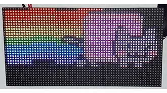
Advanced Example: Big, big flag of Wales
This example uses 4 64×32 matrices attached to a single MatrixPortal using the "serpentine" wiring style.
Place the code below on CIRCUITPY (as code.py) and the bitmap image (as wales.bmp). You can change the bitmap to any other file that works with OnDiskBitmap, up to 128x64 pixels. No additional libraries are required. You can adapt it to other boards by changing the lines that create the RGBMatrix object.
# SPDX-FileCopyrightText: 2021 Jeff Epler for Adafruit Industries
#
# SPDX-License-Identifier: MIT

# Minimal example displaying an image tiled across multiple RGB LED matrices.
# This is written for MatrixPortal and four 64x32 pixel matrices, but could
# be adapted to different boards and matrix combinations.
# No additional libraries required, just uses displayio.
# Image wales.bmp should be in CIRCUITPY root directory.

import board
import displayio
import framebufferio
import rgbmatrix

displayio.release_displays() # Release current display, we'll create our own

# Create RGB matrix object for a chain of four 64x32 matrices tiled into
# a single 128x64 pixel display -- two matrices across, two down, with the
# second row being flipped. width and height args are the combined size of
# all the tiled sub-matrices. tile arg is the number of rows of matrices in
# the chain (horizontal tiling is implicit from the width argument, doesn't
# need to be specified, but vertical tiling must be explicitly stated).
# The serpentine argument indicates whether alternate rows are flipped --
# cabling is easier this way, downside is colors may be slightly different
# when viewed off-angle. bit_depth and pins are same as other examples.
MATRIX = rgbmatrix.RGBMatrix(
    width=128, height=64, bit_depth=6, tile=2, serpentine=True,
    rgb_pins=[board.MTX_R1,
              board.MTX_G1,
              board.MTX_B1,
              board.MTX_R2,
              board.MTX_G2,
              board.MTX_B2],
    addr_pins=[board.MTX_ADDRA,
               board.MTX_ADDRB,
               board.MTX_ADDRC,
               board.MTX_ADDRD],
    clock_pin=board.MTX_CLK, latch_pin=board.MTX_LAT,
    output_enable_pin=board.MTX_OE)

# Associate matrix with a Display to use displayio features
DISPLAY = framebufferio.FramebufferDisplay(MATRIX, auto_refresh=False,
                                           rotation=0)

# Load BMP image, create Group and TileGrid to hold it
FILENAME = "wales.bmp"

# CircuitPython 6 & 7 compatible
BITMAP = displayio.OnDiskBitmap(open(FILENAME, "rb"))
TILEGRID = displayio.TileGrid(
    BITMAP,
    pixel_shader=getattr(BITMAP, 'pixel_shader', displayio.ColorConverter()),
    tile_width=BITMAP.width,
    tile_height=BITMAP.height
)

# # CircuitPython 7+ compatible
# BITMAP = displayio.OnDiskBitmap(FILENAME)
# TILEGRID = displayio.TileGrid(
#     BITMAP,
#     pixel_shader=BITMAP.pixel_shader,
#     tile_width=BITMAP.width,
#     tile_height=BITMAP.height
# )

GROUP = displayio.Group()
GROUP.append(TILEGRID)
DISPLAY.show(GROUP)
DISPLAY.refresh()

# Nothing interactive, just hold the image there
while True:
    pass