Piranha Pi Camera
2025-09-05 | By Adafruit Industries
License: See Original Project 3D Printing Camera LCD / TFT Raspberry Pi MCU
Courtesy of Adafruit
Guide by Ruiz Brothers
Overview
Build a Piranha Plant themed camera using a Raspberry Pi 5!
The Warp Pipe-shaped base houses the Pi 5 with a fan and a 4" touch screen.
A camera module is housed inside the Piranha mouth. The case has access to the USB ports with vents on the side to keep the Pi cool.
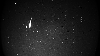
Build a timelapse rig with the sleeve to mount to a tripod. Capture stunning timelapses with dynamic exposure thanks to the HDR mode.
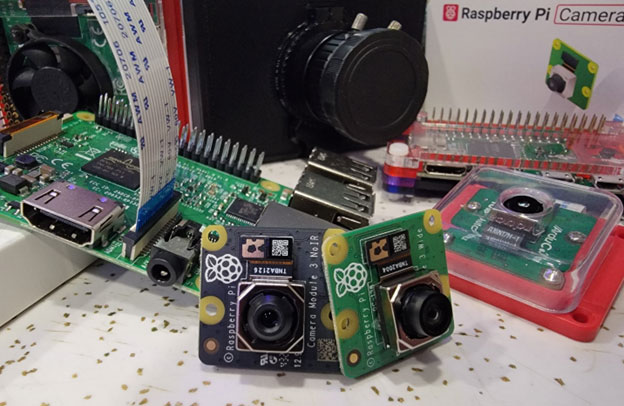
The wide angle camera module V3 features autofocus and a 12-megapixel sensor and an HDR mode, giving you excellent image quality.
High dynamic range means you can capture perfect exposures in timelapse videos.
Parts
Raspberry Pi Camera Module 3 - 12MP 120 Degree Wide Angle Lens
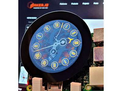
Pimoroni HyperPixel - 4.0" Hi-Res Display for Raspberry Pi
Official Raspberry Pi 45W USB-C Power Supply
13 x M2.5x6mm Screws
4 x M2.5x5mm Screws
2 x M2x6mm Screws
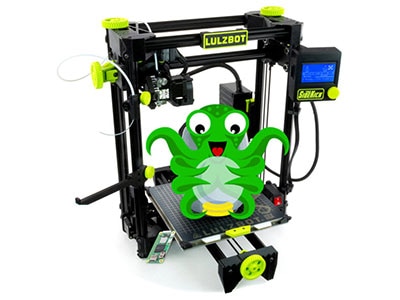
3D Printing
Parts List
STL files for 3D printing are oriented to print "as-is" on FDM style machines. Most parts are designed to 3D print without any support material. Original design source may be downloaded using the link below.
Download Pi Piranha Cam STLs + 3MF
Slice with settings for PLA material.
The parts were sliced using CURA using the slice settings below.
PLA filament 220c extruder
0.2 layer height
10% gyroid infill
60mm/s print speed
60c heated bed
Assemble
Mount the fan
Plug the fan cable into the port by the headers on the Pi. Align the sticky thermal pads to the chips on the Pi.
Gently apply pressure to the spring screws to the inner screw (the two holes without the yellow outlines) mounts on the Pi.
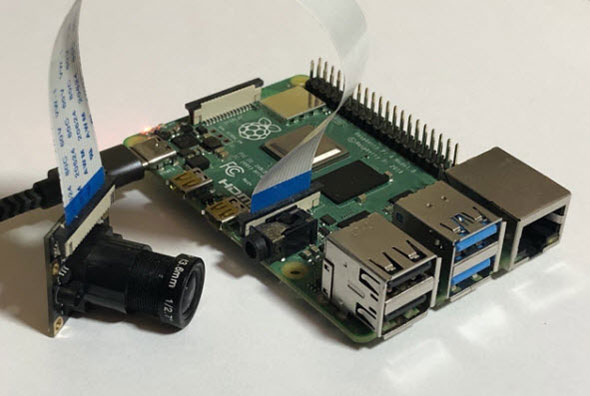
Camera ribbon cable
Insert the included 150mm camera cable into the CAM/DISP 0 port as follows:
Gently pull the two connector latches on each side of the camera ribbon connector.
The cable should face toward the USB A ports. Press fit the ribbon cable into the camera port.
Push each side of the latch connector one at a time to firmly attach the ribbon cable.
Mount Pi
Align the USB A ports to the cutout on the bottom printed case.
Fasten it using three M2.5x6mm screws.
Leave the standoff next to the USB C port without a screw to accommodate the display standoff.
Display standoff
Use one of the Hyper Pixel standoffs (included) to help level the display when attached to the Pi.
Attach the standoff next to the longer ribbon cable port.
Make sure the camera ribbon cable is laying towards the USB A ports.
Add the included header extender to the display and mount to the headers on the Pi.
Peel the protective film
Remove the protective film off the display before attaching the front case.
Slide the front case rails under the display with the USB port cutout first.
Press fit the rails one side at a time to snap fit together.
Assemble stem
Align the stem to the sleeve and fasten the tabs on the sides with two M2.5x6mm screws.
The front screw holes use two M2.5x5mm screws, fasten from underneath the sleeve.
Stem ribbon cable
Align the sleeve to the screen cutout.
Insert the ribbon cable into the stem cavity.
Place bottom mouth
Align the ribbon cutout to the bottom mouth part and place over the screw mounts on the end of the stem.
Pass the ribbon cable through the cutout.
Fasten the mouth to the stem. The two screws on the outer side are M2.5x6mm long. The two center screws are M2.5x5mm long.
Attach the camera module
Gently pull the two connector latches on each side of the camera module.
Press fit the ribbon cable into the camera port.
Push each latch connector one at a time to firmly attach the ribbon cable.
Angle the camera module to press fit into the bottom nubs.
Fasten with two M2x6mm screws to the top standoffs.
Attach the top mouth
Place the top mouth part over the screw holes and fasten with three to six M2.5x6mm screws.
To secure the sleeve to the case, use two M2.5x6mm screw on the sides.
Attach the leaf
The leaf press fits by gently bending one side of the cutout and place over the stem.
Tripod attachment
The tripod sleeve press fits to the bottom of the case and can be fasten with two M2.5x6mm screws.
A 3/8" to 1/4" adapter screw threads into the screw hole.
Use
The default installation of Raspberry Pi OS includes support for the V3 cameras. A full list of commands is linked below.
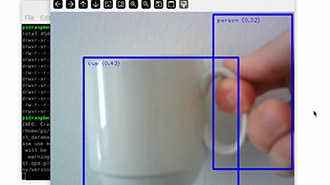
Preview camera
Open a terminal window and load a preview window to frame up the camera.
rpicam-hello -t0 --hdr
Timelapse settings
We used the settings below for quick on location timelapses.
For 10 mins it will take one picture every 1 second.
rpicam-still -t 600000 --timelapse 1000 --datetime –hdr