Mfr Part # SC0020
SBC 1.0GHZ 1 CORE 512MB RAM
Raspberry Pi
License: See Original Project Camera Wearables Raspberry Pi SBC
Courtesy of Adafruit
Guide by Phillip Burgess and 1 other contributor
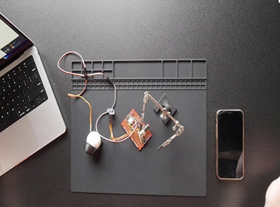
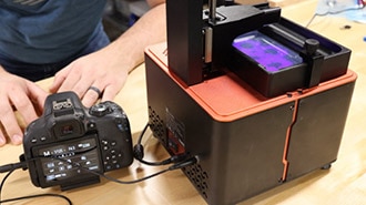
Worn on a lanyard or clipped to a pocket or pack, this adorable camera snaps a photo every few seconds. Slide the SD card into your computer to review the day’s activities or merge all the images into a timelapse animation.
Powered by the diminutive and affordable Raspberry Pi Zero, this DIY project is eminently configurable and customizable!
Parts and Tools Required
The “canonical” build in this guide is illustrated with the following parts:
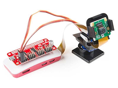
Raspberry Pi Model Zero W version 1.3 or later (with camera connector) or Raspberry Pi Zero 2 W
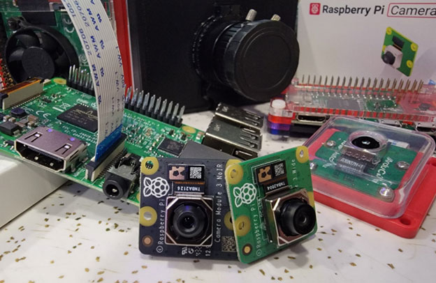
Raspberry Pi Camera (any version — 8 megapixel v2 or original 5 MP — even infrared if you like)
4GB or larger micro-SD card
PowerBoost 500 Charger (not the PowerBoost 500 Basic; must be the 500C!)
Breadboard-Friendly SPDT Slide Switch
LED sequin, any color
Soldering iron, wire and related paraphernalia
3D printer and filament
Craft glue such as E6000 or Krazy Glue®
The first three listed items are available in packs with either a regular or infrared camera.
The example software will run on any Raspberry Pi computer. Since Pi Zero supplies are constrained…or if you just want to use a different board or battery, or create your own enclosure in another medium…you might instead consider:
Raspberry Pi Model A+ (any Pi can work, but most are bulkier and draw more power)
All but the Pi Zero can use the standard flex cable already included with the camera. Custom cables for novel form-factors are optional.
You can skip the PowerBoost and power the Pi directly from a USB phone charger battery.
For the LED sequin, you can substitute a regular through-hole LED (any color) and resistor (75 to 500 Ohm).
Likewise, most any pushbutton or switch can be substituted if you’re not using the 3D-printed case.
The 500 mAh battery is good for about 2 hours run time. If you want to keep it going all day, you could design an enclosure around a larger battery…or simply plug the PowerBoost into a USB phone charger to greatly extend its life!
You may need some additional parts depending on the installation procedure used (perhaps a USB flash card reader, or a second Raspberry Pi during setup, etc.). Read through the whole guide and check your parts stash before making any purchasing decisions.
3D Printing
This case does not fit the Raspberry Pi Zero 2 W due to the size of the WiFi module. It was designed for the Pi Zero.
Let’s start with the printing first. You can work on the software and electronics while the printer runs the job.
If doing your own custom build — for example, if using a Raspberry Pi Model A+ or a different battery — skip ahead to the next page. The 3D-printed parts are specifically designed around the Pi Zero and components listed previously.
Download 3D Files from Thingiverse
Download 3D Files from Youmagine
The 3D parts will fit on even the smallest of printers, no problem there. 20% infill works well, and no support material is required.
PLA filament is easiest to work with. If printing in ABS instead, you might need to scale the model up slightly (about 2%) to allow for shrinkage…the parts tolerances are very tight.
No fasteners are used. Instead, parts can be held with small dabs of E6000 craft glue, or cyanoacrylate “Krazy” glue.
The clip glues to a slot in the bottom case.
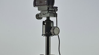
The tripod mount and tripod base glue together the “tall” way…then the camera (with clip) can slide onto this or be removed and worn.
Software
This guide was originally written with instructions providing a ready-made image but became quite outdated. Rather than continually building new images from scratch, it's much easier to describe how you can put together all the software parts manually.
The “Using It” page of this guide provides configuration and operation details…but if nothing else: it’s super especially important that you press and hold the halt button and then wait about 20 seconds before switching the camera off. Don’t just turn off the power when you’re done…otherwise you may lose images and/or corrupt the SD card and have to start over.
By default, the camera will capture a 1280x720 pixel JPEG image every 15 seconds, recording it to the SD card in the “timelapse” folder. You can change these options by inserting the card in your regular computer and editing a configuration file, explained on the “Using It” page.
Start with the lite version of the latest existing Raspberry Pi OS. It's easiest to use the Raspberry Pi Imager, which can configure Wi-Fi for you ahead of time.
Then install all the software and scripts needed for the camera project. The project has been updated to work on top of Blinka, so the easiest way to do this is to follow the installation page in the Blinka guide. This will get a virtual environment installed as well as Blinka.
This requires a Raspberry Pi with a network connection, which can be a nuisance if you’re working directly on the Pi Zero (rather than the Zero W). It’s usually easiest to set up the SD card on a more capable system (like a Raspberry Pi 3) and then move the finished card over to the Pi Zero; it’ll boot all the same.
The latest versions of the Raspberry Pi OS automatically expand the file system on the first boot. If you followed the Blinka guide and ran the install script, the camera should already be enabled. If not, you can enable it through the raspi-config utility.
Next download the timelapse script with the following commands:
sudo apt install -y wget
cd ~
wget https://github.com/adafruit/Adafruit_Learning_System_Guides/raw/main/Wearable_Time_Lapse_Camera/timelapse.py
Alternatively, if you’re logged in remotely via ssh, you can copy-and-paste the script below into that file. Since this will be located in the Pi’s /boot directory (which also shows up on regular Windows or Mac computers), you can save the script on your desktop computer and move it to the card later.
# SPDX-FileCopyrightText: 2024 Melissa leBlanc-Williams for Adafruit Industries
#
# SPDX-License-Identifier: MIT

#!/usr/bin/env python3

import os
import re
import time
import board
import digitalio

# Timelapse script, because timelapse options in raspistill don't power
# down the camera between captures. Script also provides a camera busy LED
# (v2 cameras don't include one) and a system halt button.
# Limitations: if DEST is FAT32 filesystem, max of 65535 files in directory;
# if DEST is ext4 filesystem, may have performance issues above 10K files.
# For intervals <2 sec, better just to use raspistill's timelapse feature.

# Configurable stuff...
INTERVAL = 15  # Time between captures, in seconds
WIDTH = 1280  # Image width in pixels
HEIGHT = 720  # Image height in pixels
QUALITY = 51  # JPEG image quality (0-100)
DEST = "/boot/timelapse"  # Destination directory (MUST NOT CONTAIN NUMBERS)
PREFIX = "img"  # Image prefix (MUST NOT CONTAIN NUMBERS)
HALT_PIN = board.D21  # Halt button GPIO pin (other end to GND)
LED_PIN = board.D5  # Status LED pin (v2 Pi cam lacks built-in LED)
COMMAND = "libcamera-still -n --width {width} --height {height} -q {quality} --thumb none -t 250 -o {outfile}" # pylint: disable=line-too-long
# COMMAND = "raspistill -n -w {width -h {height} -q {quality} -th none -t 250 -o {outfile}"

def main():
    prevtime = 0  # Time of last capture (0 = do 1st image immediately)
    halt = digitalio.DigitalInOut(HALT_PIN)
    halt.switch_to_input(pull=digitalio.Pull.UP)
    led = digitalio.DigitalInOut(LED_PIN)
    led.switch_to_output()

    # Create destination directory (if not present)
    os.makedirs(DEST, exist_ok=True)

    # Find index of last image (if any) in directory, start at this + 1
    files = os.listdir(DEST)
    numbers = [
        int(re.search(r"\d+", f).group())
        for f in files
        if f.startswith(PREFIX) and re.search(r"\d+", f)
    ]
    numbers.sort()
    frame = numbers[-1] + 1 if numbers else 1
    currenttime = time.monotonic()

    while True:
        while time.monotonic() < prevtime + INTERVAL:  # Until next image capture time
            currenttime = time.monotonic()
            # Check for halt button -- hold >= 2 sec
            while not halt.value:
                if time.monotonic() >= currenttime + 2:
                    led.value = True
                    os.system("shutdown -h now")
        outfile = f"{DEST}/{PREFIX}{frame:05}.jpg"
        # echo $OUTFILE
        led.value = True
        os.system(
            COMMAND.format(width=WIDTH, height=HEIGHT, quality=QUALITY, outfile=outfile)
        )
        led.value = False
        frame += 1  # Increment image counter
        prevtime = currenttime  # Save image cap time


if __name__ == "__main__":
    main()
The file timelapse.py will contain our camera script. To run it, use the following command:
sudo -E env PATH=$PATH python3 ~/timelapse.py
There may be some info and warnings displayed when you run it. This is normal. It should still function correctly.
To launch the script automatically on startup, edit the file /etc/rc.local and insert the following line near the end, just before the final exit 0. If you are using a different username than pi, you will want to change ~pi to ~yourusername.
sudo ~pi/env/bin/python3 ~pi/timelapse.py &
Finally, follow the Resizing the Raspberry Pi Boot Partition guide to expand the boot partition.
Alternatively, you can use your home folder and update the DEST path in the script variables. However, it may be slightly harder to access the photos on some systems.
Camera settings and such are explained on the “Using It” page.
Wiring
Wiring Components
Once the parts are 3D printed and software is burnt and ready for use, we can start wiring the components.
Slide Switch
Let's start with the slide switch. We'll need two wires here, each about 8cm in length. Remove about 5mm of insulation from the tips of each wire and “tin” them (apply a layer of solder) — this prevents the stranded wires from fraying.
Next, remove one of the three legs from the switch (can be furthest one from left or right, not the middle.) Then, trim the two remaining legs short (about half length).
Now connect a wire to each leg on the slide switch by soldering them together.
LED Sequin
For the LED Sequin, we'll need two wires about 7cm in length. Strip and tin the tips of these wires. Then, solder them to the back of the LED Sequin PCB. I suggest tinning the pads on the LED Sequin first.
6mm Slim Button
We'll need two wires about 7cm in length for the slim button. Trim the two legs to about half their size. Then, tin the legs from the inside. Solder wires to the legs, pointing inwards - reference the photo for ideal location.
Raspberry Pi Power Wires
We'll need two wires to connect the PowerBoost 500C to the Raspberry Pi. These can be about 8cm in length.
Connect Switch to PowerBoost
Solder one of the wires from the slide switch to the EN (enable) pin on the PowerBoost 500C, and the other to GND (ground). Polarity doesn't matter here.
Connect Pi Power Wires to PowerBoost
Now solder the two wires for the Raspberry Pi to the postive+ and negative- pins on the PowerBoost 500C.
With wires now added to the LED, button and PowerBoost, just a few easy connections are required to the Raspberry Pi:
PowerBoost 500C output connects to 5V and GND.
LED sequin + connects to GPIO5, – to GND.
Halt button connects to GPIO21 and GND.
If required, the LED and button pins can be changed; this is explained on the “Using It” page. Maybe you find it easier to route the wires to a different spot or are building a camera with custom features.
Here’s a full map of the Pi’s GPIO header, with our connections highlighted in blue. Although this project does not use a PiTFT display, those pins are marked “maybe” off-limits in the diagram below, since adding a screen (with a different enclosure) might be a popular upgrade project for ambitious makers.
Connect PowerBoost to Raspberry Pi
Solder the positive+ wire from the PowerBoost 500C to 5V on Raspberry Pi. Solder the negative- wire from the PowerBoost 500C to GND on Raspberry Pi. Best location is to wire them from the bottom of the Pi's PCB.
Be extra careful to get + and – to the correct pins or you’ll fry your rare and elusive Pi Zero board. Double-check all the connections before finishing up and switching on!
Connect Button to Raspberry Pi
Solder the two wires from the 6mm slim button to the GPIO on the bottom of the Raspberry Pi. One wire to GPIO21 and the other to ground.
Connect LED Sequin to Raspberry Pi
Solder the postive+ wire from the LED Sequin to GPIO5 on the top of the Raspberry Pi, and the negative- wire to ground.
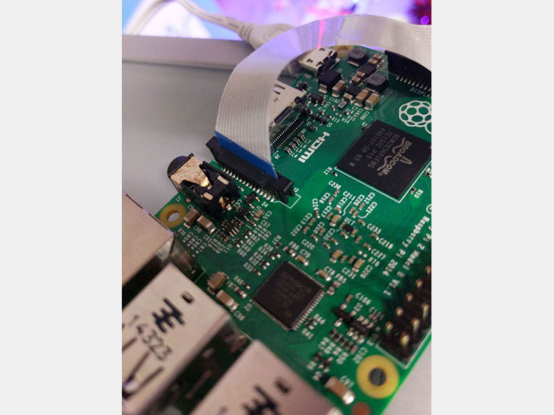
Install Ribbon Cable
Now the flex cable can be installed between the camera and Raspberry Pi board. The photo shows the correct orientation for each end.
Make sure the cable is seated correctly, and the connectors are latched at both ends. (If you end up with occasional green photos, it’s usually a misaligned cable.)
Peel the protective plastic tape off the camera lens.
Test Circuit
OK, now most of our components are wired up. We can run a test to see if everything works.
Insert the SD card to the Pi.
Connect the Pi camera module to the Pi.
Plug in the JST connector from the 500mAh LiPo battery to the PowerBoost 500C.
If the blue LED turns on, the slide switch is on, and Pi will power up. If not, slide the switch to turn it on. The Pi will take about ~1min to boot up (on initial startup). You should see the LED sequin turn on each time the Pi takes a photo.
Allow it to run for a few minutes collecting photos, so you can confirm the camera connection is solid before sealing everything up.
If it’s all working as expected, hold down the 6mm slim button for about ~3 seconds and wait about 30 seconds for the Pi to safely shut down. Then, turn off the PowerBoost 500C with the slide switch.
Remove the SD card from the Pi and insert it into your computer. Your photos will show up in the “timelapse” folder.
Once you’re satisfied everything’s operational, we can move on to mounting the circuit into the 3D-printed case…
Assembly
Install Button
The 6mm slim button is a bit tricky to install in the case. You'll have to remove it from the Pi GPIO by desoldering the wires. Once it's free, thread the two wires from the button into the case - refer to the photos for the location. Then, push the button through the hole. Press it down until the button is positioned properly. Once nestiled in place, the button will stay put when pressed.
Now you can solder the wires back onto the GPIO of the Raspberry Pi.
Install PowerBoost 500C
With the battery plugged into the PowerBoost 500C, insert the PowerBoost 500C into the case and line up the mounting holes with the standoffs. Press it down so the nubs from the standoffs snap into the mounting holes.
If the nubs aren’t “snappy” enough, you can add some small dabs of E6000® or Krazy Glue® to keep the board in place.
Install Battery
Fit the 500mAh lip battery into case. Carefully nestile the JST cable from the battery into the case.
Install LED Sequin
Lay the LED Sequin PCB over the cavity on the case cover. Orient the Sequin so the SMD LED is poking through the opening. You'll need a piece of mounting tack or glue to keep it in place - It may snap into place depending on your printers tolerances.
Install Pi Camera
Orient the Pi camera so the lens pokes through the hole. Line up the nubs from the standoffs with the mounting holes on the Pi camera PCB. Press the Pi camera so it's flush with the standoffs.
Install Raspberry Pi
The Raspberry Pi will lay over the Pi camera module. Line up the nubs from the standoffs with the mounting holes on the Pi. Press the Pi PCB down until it snap fits into the nubs.
Secure Pi Camera Cable
Bend the excess cable from the Pi camera module so its over the bottom of the Pi PCB. I recommend using small pieces of mounting tack to keep the ribbon cable from unfolding.
Install Slide Switch
The slide switch will rest on the platform over the 6mm slim button. You may need some mounting tack to keep in place while closing the case.
Close Case!
Now it's time to join the cover and case together. Make sure any excess wires are tucked into the case or cover. Start by inserting the cover into the case at an angle, with the ports from the Raspberry Pi first. Then, press the cover into the case so it snaps fit.
If find the case won't close, you may need to install the switch onto the cover instead - if it still doesn't close, thoroughly inspect the wires and components to see if something is blocking the lip of the cover.
Install Wearable Clip
If you plan on wearing the Pi camera, we provided a little clip. There's a small little "slit" on the back of the case - press the connector from clip into the slit. You’ll probably want some glue to keep it in place.
Optional: Extra Lens
You can optionally add lenses to increase the viewing angle. I got this 0.68X wide angle lense from Amazon.com - it's normally used for mobile phones. It uses a magnet and metal ring with a stick adhesive backing so you can easily add / remove the lens.
Using It
The camera software works on its own…there’s no buttons or anything to fiddle with to get it started. Just turn the power switch on…once the system is booted (maybe 30 seconds or so) it will begin capturing images (first-time boot may take about a minute longer as it resizes the filesystem and such). The status LED will turn ON while the camera is taking a picture.
To turn the camera off, press and hold the halt button for at least 2 seconds. The status LED will turn ON while the system performs a clean shutdown (about 20 seconds), then OFF to indicate it’s safe to turn the power switch off.
Always use the halt button before powering off the camera. Don’t just switch it off or you risk losing images or having to re-do the whole SD card.
When the system is powered off, you can remove the micro-SD card and install it in a USB reader on your regular computer. The images will be inside a folder called “timelapse” and are numbered sequentially…img00001.jpg, img00002.jpg, img00003.jpg and so forth.
After transferring images off the card, you can delete these files (or the whole timelapse folder) and the next recording will begin back at #00001. Or if you leave the images there, it will begin recording at the next number in the sequence.
Do not move, alter, or delete any files other than the images in the timelapse folder. The Raspberry Pi requires these to run.
Settings
By default, the software will capture a 1280 by 720-pixel JPEG image every 15 seconds. You can change these settings by editing the file timelapse.py on the SD card using any text editor. These configurable values are near the top of the file:
# Configurable stuff...
INTERVAL = 15 				# Time between captures, in seconds
WIDTH = 1280  				# Image width in pixels
HEIGHT = 720  				# Image height in pixels
QUALITY = 51  				# JPEG image quality (0-100)
DEST = "/boot/timelapse"   	# Destination directory (MUST NOT CONTAIN NUMBERS)
PREFIX = "img"  			# Image prefix (MUST NOT CONTAIN NUMBERS)
HALT_PIN = board.D21  		# Halt button GPIO pin (other end to GND)
LED_PIN = board.D5  		# Status LED pin (v2 Pi cam lacks built-in LED)

COMMAND = "libcamera-still -n --width {width} --height {height} -q {quality} --thumb none -t 250 -o {outfile}"
# COMMAND = "raspistill -n -w {width -h {height} -q {quality} -th none -t 250 -o {outfile}"With this script there is a practical minimum interval of about 2 seconds between captures (maybe longer for larger images); if you need anything faster than that, it’s best to use the time lapse features built into the libcamera-still or raspistill utility itself. This is documented on the Raspberry Pi web site.
The GPIO pins used by the halt button and status LED can be changed in the script if you’ve wired yours up differently.
Since libcamera-still has replaced for raspistill, this is now the default. If you are on an older system, you can use the equivalent raspistill line.
Direct Sunlight
If you find a lot of images are coming back oddly exposed, the camera might need a little more “wakeup time” before capturing an image. Look for the following line (up just a few lines from end of the script) and change “250” to a larger value, perhaps 1000 (this is the wakeup time in milliseconds; 1000 = 1 second):
libcamera-still -n --width {width} --height {height} -q {quality} --thumb none -t 1500 -o {outfile}or if you are using raspistill:
raspistill -n -w {width -h {height} -q {quality} -th none -t 1500 -o {outfile}There are more settings for controlling exposure, ISO, etc…see link below…
Gotchas and Things to Know
With this or any other battery-powered Raspberry Project, there’s a small possibility of losing data (or even corrupting the SD card and having to start over) should the battery become depleted during use…similar to switching the device off without using the halt button.
One way to reduce (but not eliminate) this risk is to add a “sync” command immediately after the “libcamera-still” command, which forces the completion of all pending file writes:
os.system(
    COMMAND.format(width=WIDTH, height=HEIGHT, quality=QUALITY, outfile=outfile)
)
os.system("sync")The extra time needed for this sync operation means the practical minimum INTERVAL value will be longer…perhaps 10 seconds. This is why it’s not done by default.
Adjusting Camera Settings
The libcamera-still command (as it was with the older raspistill command) has a huge number of options…you can tweak exposure and white balance settings, image size, add interesting “painterly” effects to the image…it’s way beyond the scope of this guide, so if you’d like to dig deeper, please refer to the Pi Foundation’s reference:
Official Raspberry Pi Camera Documentation
Extending Run Time
If you have a very long-time lapse project in mind that exceeds the longevity of the built-in battery (about 2 hours), you can use a higher capacity USB phone charger battery connected one of two ways:
To the PowerBoost’s USB charge port. This will top off the PowerBoost’s battery while also running the Pi.
Directly to the Pi’s USB power port. Leave the PowerBoost switched OFF in this case, or there will be…trouble.
In either case, you do still need to use the halt button before switching off or disconnecting power.
SD Card Limitations
The /boot filesystem uses a Windows “FAT32” directory structure. This limits the timelapse directory to a maximum of 65,535 images. The script doesn’t enforce any specific checks on this, since other limiting factors (battery longevity, card capacity, etc.) are more likely to come into play much sooner.
The startup file system consistency check (fsck) on the /boot partition has been disabled in the ready-made SD image. If a large number of images (several thousand) are present on the card, boot time is inordinately long with this check in place. If you really want that boot-time check, you’ll need to familiarize yourself with and edit /etc/fstab.
Between this and the battery concerns, copying images off the card at every convenient opportunity is recommended. Also, if you’ve rolled your own SD card, making a backup image is recommended.
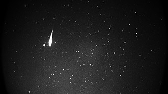
Merging Stills into Video or GIF
Combining the captured images into a video or GIF you can share will depend on what software you have access to and are familiar with. For example, Adobe Premiere or AfterEffects have fancy GUIs (but cost may be prohibitive if you don’t already use these tools), or there are free command-line tools like ffmpeg or ImageMagick’s convert.
Covering every tool for every likely operating system is beyond the scope of this guide. If it’s an unfamiliar process, try Google searching for “jpg to video windows” or “jpg to video mac” or similar. So many options!
Just one example…in Adobe Photoshop CC, it’s possible through a roundabout sequence of operations…
File→Scripts→Load Files into Stack…
In pop-up window, click “Browse” and select image files, then “OK.”
In Timeline window, “Create Frame Animation.”
In Timeline menu, “Make Frames from Layers.”
Then the usual frame animation tools (timing, etc.) can be used to create a video (File→Export→Render Video…) or animated GIF (File→Export→Save for Web (Legacy)…).