Mfr Part # 5302
KB2040 RP2040 KEE BOAR DRIVER
Adafruit Industries LLC
License: Attribution-Share Alike 3D Printing Motors Raspberry Pi MCU
Courtesy of Adafruit
Guide by Ruiz Brothers and Liz Clark
Overview
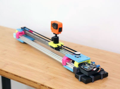
Slide & Pan
This project uses two stepper motors to create smooth cinematic motion for capturing video or timelapse photography. You can use it to automate both trucking and panning for beautiful compound camera motion. It features a 1.3in TFT screen for displaying a user interface and a rotary encoder for controlling the stepper motors.
It's powered by an Adafruit KB2040 running CircuitPython. The TMC2209 stepper motor drivers offer smooth and silent micro stepping.
The software features a mode for capturing timelapses and a one-shot mode for filming video.
DIY Motorized Slider
3D printed parts support two pieces of aluminum extrusion. A timing belt and pulley wheels are used to slide the carriage along the profile offering about 16 inches (40cm) of travel. A second motor is dedicated for panning offering a bit over 180 degrees.
A custom PCB reduces the amount of wiring connecting the microcontroller, TFT display, buck converter and two stepper motor drivers. It runs off a 12V AA battery pack making the build portable for filming outdoors.
Crank It!
Use the rotary encoder to set the start and ending positions of the panning motor. A 3D printed rotary handle lets you crank the motor making an intuitive interface for setting the panning stepper motor.
This learn guide assumes prior experience with electronics, 3D printing, mechanical engineering and videography. It is not recommended for beginner makers but is achievable with patience and the willingness to learn new skills.
Parts from Adafruit
Adafruit 1.3" 240x240 Wide Angle TFT LCD Display with MicroSD
8 x AA battery holder with 5.5mm/2.1mm Plug and On/Off Switch
2 x Adafruit TMC2209
2 x Micro Switch
2 x Slotted Aluminum Extrusion
1 x DC barrel jack
1 x Terminal Block
1 x Socket Headers
Parts from Amazon
2 x Stepper Motor
1 x 6008-2RS Bearing
4 x Pulley Wheels with Bearing Idler
1 x GT2 Timing Pulley
1 x GT2 Timing Belt
1 x 1/4"-20 x 1/2" Tripod Screw
1 x 1/4"-20 Rubber Washer
1 x 8x AA Rechargeable Batteries
Circuit Diagram
This is a big build so there's a PCB to help keep the wiring nice and tidy. The PCB uses headers to easily plug in the breakouts and KB2040. The rotary encoder, terminal blocks, DC jack and JST connectors get soldered directly to the board. There are labels on the silkscreen to help identify the correct placement for everything. The Eagle files and Gerber files are available on GitHub if you want to order your own.
Schematic and Fab Print
dimensions are in inches
Fritzing
Of course, if you're feeling adventurous, you can forego the PCB and wire the breakouts and components directly.
Power
DC Jack 12V Power to MPM3601 Vin (red wire)
DC Jack GND to MPM3601 GND (black wire)
DC Jack 12V Power to TMC2209 1 terminal block + (red wire)
DC Jack GND to TMC2209 1 terminal block - (black wire)
DC Jack 12V Power to TMC2209 2 terminal block + (red wire)
DC Jack GND to TMC2209 2 terminal block - (black wire)
MPM3601 5V to KB2040 RAW (red wire)
MPM3601 GND to KB2040 G (black wire)
Rotary Encoder
Encoder button to KB2040 D2 (purple wire)
Encoder GND to KB2040 G (black wire)
Encoder pin A to KB2040 D7 (orange wire)
Encoder pin B to KB2040 D6 (cyan wire)
TFT
TFT Vin to KB2040 3V (red wire)
TFT Gnd to KB2040 G (black wire)
TFT SCK to KB2040 SCK (green wire)
TFT MOSI to KB2040 MOSI (blue wire)
TFT TCS to KB2040 D10 (white wire)
TFT RST to KB2040 D9 (grey wire)
TFT DC to KB2040 D8 (pink wire)
Limit Switches
Limit switch GND to KB2040 G (black wire)
Limit switch 1 output to KB2040 A2 (ochre wire)
Limit switch 2 output to KB2040 A3 (brown wire)
TMC2209 Breakout 1
KB2040 3V to TMC2209 1 VDD (red wire)
KB2040 G to TMC2209 1 GND (black wire)
KB2040 TX to 2.2K resistor (white wire)
KB2040 RX to 2.2K resistor (green wire)
TMC2209 1 UART to RX side of resistor (purple wire)
TMC2209 1 1A to stepper motor coil 1 positive (green wire)
TMC2209 1 1B to stepper motor coil 1 negative (yellow wire)
TMC2209 1 2A to stepper motor coil 2 positive (red wire)
TMC2209 1 2B to stepper motor coil 2 negative (black wire)
TMC2209 Breakout 2
KB2040 3V to TMC2209 2 VDD (red wire)
KB2040 G to TMC2209 2 GND (black wire)
KB2040 D4 to 2.2K resistor (yellow wire)
KB2040 D5 to 2.2K resistor (blue wire)
TMC2209 2 UART to RX side of resistor (purple wire)
TMC2209 2 1A to stepper motor coil 1 positive (green wire)
TMC2209 2 1B to stepper motor coil 1 negative (yellow wire)
TMC2209 2 2A to stepper motor coil 2 positive (red wire)
TMC2209 2 2B to stepper motor coil 2 negative (black wire)
Ordering PCB
OSH Park
The PCB is available to purchase from OSH park using the green button link below or from the projects permalink.
JLCPCB / PCBWay
Alternative fabrication services like JLCPCB or PCBWay are great options. You can get your boards made quickly and just use the default options. The boards are made in 1-2 days, and DHL shipping to the US from China takes less than a week. Just upload the Gerber zip file and follow the ordering process. You can also check out PCB Builder | DigiKey.
Note: At the time this guide was written, the tariff situation between the US and China was changing every several days. If there are tariffs for goods from China, JLCPCB and PCBWay orders may come with unexpected tariff costs. OSH Park is in the US and there are no tariff costs within the US. We suggest you do some research as to costs prior to placing an order with a PCB board vendor.
Download PCB Gerber ZIP file from GitHub
CAD Files
CAD Assembly
The main assembly is available in Fusion 360 and STEP file formats. This includes all of the 3D printed parts and electronic components used in the project. Use the main assembly to create any edits, updates, or modifications.
3D Printed Parts
Individual 3MF files for 3D printing are oriented and ready to print on FDM machines using PLA filament. Original design source may be downloaded using the links below.
Support Material
Enable support material for the left and right Lever Cap parts. In the BambuStudio slicing app, enable the Support critical regions only option under the Support section. This will only apply supports to the large surface areas that need support. In other slicing applications, support blockers might be need.
Build Volume
The parts require a 3D printer with a minimum build volume of:
140mm (X) x 170mm (Y) x 30mm (Z)
Install CircuitPython
CircuitPython is a derivative of MicroPython designed to simplify experimentation and education on low-cost microcontrollers. It makes it easier than ever to get prototyping by requiring no upfront desktop software downloads. Simply copy and edit files on the CIRCUITPY drive to iterate.
CircuitPython QuickStart
Follow this step-by-step to quickly get CircuitPython running on your board.
Download the latest version of CircuitPython for this board via circuitpython.org
Click the link above to download the latest CircuitPython UF2 file.
Save it wherever is convenient for you.
To enter the bootloader, hold down the BOOT/BOOTSEL button (highlighted in red above), and while continuing to hold it (don't let go!), press and release the reset button (highlighted in red or blue above). Continue to hold the BOOT/BOOTSEL button until the RPI-RP2 drive appears!
If the drive does not appear, release all the buttons, and then repeat the process above.
You can also start with your board unplugged from USB, press and hold the BOOTSEL button (highlighted in red above), continue to hold it while plugging it into USB, and wait for the drive to appear before releasing the button.
A lot of people end up using charge-only USB cables and it is very frustrating! Make sure you have a USB cable you know is good for data sync.
You will see a new disk drive appear called RPI-RP2.
Drag the adafruit_circuitpython_etc.uf2 file to RPI-RP2.
The RPI-RP2 drive will disappear, and a new disk drive called CIRCUITPY will appear.
That's it, you're done! :)
Safe Mode
You want to edit your code.py or modify the files on your CIRCUITPY drive but find that you can't. Perhaps your board has gotten into a state where CIRCUITPY is read-only. You may have turned off the CIRCUITPY drive altogether. Whatever the reason, safe mode can help.
Safe mode in CircuitPython does not run any user code on startup and disables auto-reload. This means a few things. First, safe mode bypasses any code in boot.py (where you can set CIRCUITPY read-only or turn it off completely). Second, it does not run the code in code.py. And finally, it does not automatically soft-reload when data is written to the CIRCUITPY drive.
Therefore, whatever you may have done to put your board in a non-interactive state, safe mode gives you the opportunity to correct it without losing all of the data on the CIRCUITPY drive.
Entering Safe Mode
To enter safe mode when using CircuitPython, plug in your board or hit reset (highlighted in red above). Immediately after the board starts up or resets, it waits 1000ms. On some boards, the onboard status LED (highlighted in green above) will blink yellow during that time. If you press reset during that 1000ms, the board will start up in safe mode. It can be difficult to react to the yellow LED, so you may want to think of it simply as a slow double click of the reset button. (Remember, a fast double click of reset enters the bootloader.)
In Safe Mode
If you successfully enter safe mode on CircuitPython, the LED will intermittently blink yellow three times.
If you connect to the serial console, you'll find the following message.
Auto-reload is off.

Running in safe mode! Not running saved code.

CircuitPython is in safe mode because you pressed the reset button during boot. Press again to exit safe mode.

Press any key to enter the REPL. Use CTRL-D to reload.
You can now edit the contents of the CIRCUITPY drive. Remember, your code will not run until you press the reset button, or unplug and plug in your board, to get out of safe mode.
Flash Resetting UF2
If your board ever gets into a really weird state and CIRCUITPY doesn't show up as a disk drive after installing CircuitPython, try loading this 'nuke' UF2 to RPI-RP2. which will do a 'deep clean' on your Flash Memory. You will lose all the files on the board, but at least you'll be able to revive it! After loading this UF2, follow the steps above to re-install CircuitPython.
Download flash erasing “nuke” UF2
Code the Slider
Once you've finished setting up your KB2040 with CircuitPython, you can access the code, images, font and necessary libraries by downloading the Project Bundle.
To do this, click on the Download Project Bundle button in the window below. It will download to your computer as a zipped folder.
# SPDX-FileCopyrightText: 2025 Liz Clark for Adafruit Industries

#

# SPDX-License-Identifier: MIT

import time

import supervisor

import rotaryio

import keypad

import board

import busio

import displayio

from adafruit_display_text import label

from fourwire import FourWire

from adafruit_st7789 import ST7789

from adafruit_bitmap_font import bitmap_font

from adafruit_tmc2209 import TMC2209

displayio.release_displays()

RAILS = 520 # length of rails in mm

microsteps = 128

gear_ratio = 41 / 16

shot_velocities = [

20,

15,

10

]

keys = keypad.Keys((board.D2, board.A2, board.A3), value_when_pressed=False, pull=True)

encoder = rotaryio.IncrementalEncoder(board.D7, board.D6)

last_position = None

spi = board.SPI()

tft_cs = board.D10

tft_dc = board.D8

display_bus = FourWire(spi, command=tft_dc, chip_select=tft_cs, reset=board.D9)

display = ST7789(display_bus, width=240, height=240, rowstart=80, auto_refresh=False)

splash = displayio.Group()

display.root_group = splash

bitmap = displayio.OnDiskBitmap("/icons.bmp")

grid_bg = displayio.TileGrid(bitmap, pixel_shader=bitmap.pixel_shader,

tile_height=100, tile_width=100,

x=(display.width - 100) // 2,

y=(display.height - 100) // 2)

splash.append(grid_bg)

text_group = displayio.Group()

font = bitmap_font.load_font("/Arial-14.bdf")

title_text = "Camera Slider"

title_area = label.Label(font, text=title_text, color=0xFFFFFF)

title_area.anchor_point = (0.5, 0.0)

title_area.anchored_position = (display.width / 2, 25)

text_group.append(title_area)

splash.append(text_group)

font = bitmap_font.load_font("/Arial-14.bdf")

text_area = label.Label(font, text="", color=0xFFFFFF)

text_area.anchor_point = (0.5, 1.0)

text_area.anchored_position = (display.width / 2, display.height - 25)

text_group.append(text_area)

uart = busio.UART(tx=board.TX, rx=board.RX, baudrate=115200, timeout=0.1)

driver1 = TMC2209(uart=uart, addr=0)

driver2 = TMC2209(tx_pin=board.D4, rx_pin=board.D5, addr=0)

version1 = driver1.version

version2 = driver2.version

print(f"TMC2209 #1 Version: 0x{version1:02X}")

print(f"TMC2209 #2 Version: 0x{version2:02X}")

driver1.microsteps = microsteps

print(driver1.microsteps)

driver2.microsteps = microsteps

print(driver2.microsteps)

STEPS_PER_MM = 200 * microsteps / 8

driver1.direction = False

driver2.direction = True

last_pos = 0

select = 0

menu = 0

time_mode = 0

shot_mode = 0

timelapse = True

movement_time = 0

titles = ["Camera Slider", "Motor 1", "Motor 2", "Mode",

"Timelapse", "One-Shot", "Start?", "Running"]

home_text = ["Press to Begin", "0"]

motor1_text = ["Slide to Start Point", "0"]

motor2_text = ["Move to Start", "Move to End", "0"]

mode_text = ["Timelapse", "One-Shot"]

time_text = ["1", "5", "10", "15", "30"]

shot_speeds = [10, 5, 2]

speeds = []

shot_text = ["Slow", "Medium", "Fast"]

start_text = ["Go!", 0]

running_text = ["STOP!", "Pause/Resume"]

running_icons = [6, 7]

mode_icons = [3, 4]

sub_titles = [home_text, motor1_text, motor2_text, mode_text,

time_text, shot_text, start_text, running_text]

motor2_coordinates = [0.0, 0.0]

text_area.text = home_text[0]

display.refresh()

def adv_menu(m):

m = (m + 1) % 8

title_area.text = titles[m]

sub = sub_titles[m]

if m == 4:

grid_bg[0] = 3

elif m == 5:

grid_bg[0] = 4

elif m > 5:

grid_bg[0] = m - 1

else:

grid_bg[0] = m

text_area.text = sub[0]

display.refresh()

return m

motor1_movement = {

"is_active": False,

"current_step": 0,

"total_steps": 0,

"start_pos": 0,

"end_pos": 0,

"step_direction": 1,

"last_step_time": 0,

"step_interval": 0,

"is_paused": False,

"toggle_pause": False,

"stop_requested": False

}

motor2_movement = {

"is_active": False,

"current_step": 0,

"total_steps": 0,

"start_pos": 0,

"end_pos": 0,

"step_direction": 1,

"last_step_time": 0,

"step_interval": 0,

"is_paused": False,

"toggle_pause": False,

"stop_requested": False

}

# pylint: disable=too-many-branches, too-many-statements, inconsistent-return-statements

def calculate_linear_velocity(steps_per_second, clock_frequency=12000000,

micro=128, scaling_factor=6):

frequency = steps_per_second * micro

vactual = int((frequency (1 << 23)) / (clock_frequency scaling_factor))

vactual = max(-(1 << 23), min((1 << 23) - 1, vactual))

return vactual

def move_steps_over_time(camera_driver, start_position, end_position,

time_seconds, micro=128, ratio=None):

steps = abs(end_position - start_position)

if camera_driver:

direction = -1 if end_position < start_position else 1

time_seconds = time_seconds * 2

else:

direction = 1 if driver1.direction else -1

if ratio is not None:

steps = steps / ratio

total_microsteps = steps * micro

microsteps_per_second = total_microsteps / time_seconds

fCLK = 12000000

if camera_driver:

vactual = int(microsteps_per_second / (fCLK / (1 << 24)))

else:

vactual = int(microsteps_per_second / (fCLK / (1 << 27)))

velocity = max(-(1 << 23), min((1 << 23) - 1, vactual))

velocity *= direction

return velocity

def calculate_timelapse_velocity(start_position, end_position, duration_seconds, micro=128,

clock_frequency=12000000, scaling_factor=6, min_velocity=100):

total_steps = abs(end_position - start_position)

steps_per_second = total_steps / duration_seconds

full_steps_per_second = steps_per_second / micro

vactual = calculate_linear_velocity(full_steps_per_second, clock_frequency,

micro, scaling_factor)

direction = -1 if end_position < start_position else 1

if abs(vactual) < min_velocity and vactual != 0:

vactual = min_velocity * direction

return vactual

def calculate_rail_velocity(total_steps, duration_sec, direction,

is_timelapse=True, micro=128, clock_frequency=12000000):

steps_per_second = total_steps / duration_sec

full_steps_per_second = steps_per_second / micro

if not is_timelapse:

base_scaling = 1.0

min_velocity = 400

vactual = int((full_steps_per_second micro (1 << 23))

/ (clock_frequency * base_scaling))

vactual *= direction

if abs(vactual) < min_velocity:

vactual = min_velocity * direction

else:

base_scaling = 6.0

min_velocity = 50

vactual = int((full_steps_per_second micro (1 << 23)) /

(clock_frequency * base_scaling))

vactual *= direction

if abs(vactual) < min_velocity:

vactual = min_velocity * direction

vactual = max(-(1 << 23), min((1 << 23) - 1, vactual))

return vactual

def move_motor_with_rotate(driver, movement_state, start_position=None,

end_position=None, duration_sec=0, micro=128):

if start_position is not None and end_position is not None and not movement_state["is_active"]:

if timelapse:

driver.enable_motor(run_current=20)

scaling_factor = 6

min_velocity = 50

velocity = calculate_timelapse_velocity(

start_position,

end_position,

duration_sec,

micro,

scaling_factor=scaling_factor,

min_velocity=min_velocity

)

else:

driver.enable_motor(run_current=30)

velocity = calculate_rail_velocity(

int(RAILS*STEPS_PER_MM),

duration_sec,

movement_state["step_direction"],

is_timelapse=timelapse,

micro=micro

)

initial_velocity = int(velocity * 0.2)

if abs(initial_velocity) < 200:

initial_velocity = 200 * (1 if velocity > 0 else -1)

driver.rotate(initial_velocity)

movement_state["initial_velocity"] = initial_velocity

movement_state["final_velocity"] = velocity

movement_state["ramp_up_done"] = False

movement_state["ramp_up_time"] = 500

movement_state["total_steps"] = int(RAILS*STEPS_PER_MM)

movement_state["step_direction"] = 1 if end_position > start_position else -1

movement_state["start_pos"] = 0

movement_state["end_pos"] = int(RAILS*STEPS_PER_MM)

movement_state["movement_start_time"] = supervisor.ticks_ms()

movement_state["movement_duration_ms"] = duration_sec * 1000

movement_state["is_active"] = True

movement_state["is_paused"] = False

return

movement_state["total_steps"] = int(RAILS*STEPS_PER_MM)

movement_state["step_direction"] = driver.direction

movement_state["start_pos"] = 0

movement_state["end_pos"] = int(RAILS*STEPS_PER_MM)

if duration_sec > 0 and movement_state["total_steps"] > 0:

movement_state["velocity"] = velocity

driver.rotate(velocity)

movement_state["movement_start_time"] = supervisor.ticks_ms()

movement_state["movement_duration_ms"] = duration_sec * 1000

else:

default_velocity = 2000 * movement_state["step_direction"]

driver.rotate(default_velocity)

movement_state["movement_duration_ms"] = movement_state["total_steps"] * 10

movement_state["movement_start_time"] = supervisor.ticks_ms()

movement_state["is_active"] = True

movement_state["is_paused"] = False

if movement_state["is_active"] and movement_state["toggle_pause"]:

movement_state["is_paused"] = not movement_state["is_paused"]

movement_state["toggle_pause"] = False

if movement_state["is_paused"]:

driver.rotate(0)

movement_state["pause_time"] = supervisor.ticks_ms()

else:

elapsed_ms = movement_state["pause_time"] - movement_state["movement_start_time"]

remaining_ms = movement_state["movement_duration_ms"] - elapsed_ms

if remaining_ms > 0:

driver.rotate(movement_state["velocity"])

movement_state["movement_start_time"] = supervisor.ticks_ms() - elapsed_ms

else:

driver.rotate(0)

driver.disable_motor()

movement_state["is_active"] = False

if movement_state["is_active"] and movement_state["stop_requested"]:

driver.rotate(0)

driver.disable_motor()

movement_state["is_active"] = False

movement_state["stop_requested"] = False

return {

"active": False,

"complete": False,

"progress_percent": (supervisor.ticks_ms() - movement_state["movement_start_time"])

/ movement_state["movement_duration_ms"] * 100,

"stopped_by_user": True

}

if movement_state["is_active"] and not movement_state["is_paused"]:

current_t = supervisor.ticks_ms()

e = current_t - movement_state["movement_start_time"]

if e >= movement_state["movement_duration_ms"]:

print("Movement time complete!")

driver.rotate(0)

driver.disable_motor()

movement_state["is_active"] = False

return {

"active": False,

"complete": True,

"progress_percent": 100,

"stopped_by_user": False

}

return {

"active": movement_state["is_active"],

"paused": movement_state["is_paused"],

"progress_percent": (supervisor.ticks_ms() - movement_state["movement_start_time"]) /

movement_state["movement_duration_ms"] * 100

if movement_state["is_active"] else 0,

"stopped_by_user": False

}

def pause_resume_motor1():

motor1_movement["toggle_pause"] = True

def stop_motor1():

driver1.disable_motor()

driver1.reset_position()

motor1_movement["stop_requested"] = True

def pause_resume_motor2():

motor2_movement["toggle_pause"] = True

def stop_motor2():

driver2.disable_motor()

driver2.reset_position()

motor2_movement["stop_requested"] = True

def stop_all_motors():

driver1.rotate(0)

driver2.rotate(0)

driver1.disable_motor()

driver2.disable_motor()

motor1_movement["is_active"] = False

motor2_movement["is_active"] = False

motor1_movement["stop_requested"] = False

motor2_movement["stop_requested"] = False

time.sleep(0.1)

driver1.disable_motor()

driver1.reset_position()

driver2.reset_position()

while True:

if motor1_movement["is_active"]:

current_time = supervisor.ticks_ms()

elapsed = current_time - motor1_movement["movement_start_time"]

if elapsed >= motor1_movement["movement_duration_ms"]:

driver1.rotate(0)

driver1.disable_motor()

motor1_movement["is_active"] = False

if motor2_movement["is_active"]:

current_time = supervisor.ticks_ms()

elapsed = current_time - motor2_movement["movement_start_time"]

if elapsed >= motor2_movement["movement_duration_ms"]:

driver2.rotate(0)

driver2.disable_motor()

motor2_movement["is_active"] = False

if menu == 7:

active_motors = 0

progress1 = 0

progress2 = 0

if motor1_movement["is_active"]:

active_motors += 1

current_time = supervisor.ticks_ms()

elapsed = current_time - motor1_movement["movement_start_time"]

progress1 = (elapsed / motor1_movement["movement_duration_ms"]) * 100

if motor2_movement["is_active"]:

active_motors += 1

current_time = supervisor.ticks_ms()

elapsed = current_time - motor2_movement["movement_start_time"]

progress2 = (elapsed / motor2_movement["movement_duration_ms"]) * 100

if active_motors > 0:

avg_progress = (progress1 + progress2) / active_motors

text_area.text = f"{running_text[select]} {avg_progress:.1f}%"

display.refresh()

elif active_motors == 0 and (motor1_movement["movement_duration_ms"] > 0

or motor2_movement["movement_duration_ms"] > 0):

text_area.text = "Movement Complete!"

display.refresh()

event = keys.events.get()

if event:

if event.pressed:

print(f"{event.key_number} pressed")

if event.key_number == 0:

if menu == 0:

menu = adv_menu(menu)

elif menu == 2:

if select == 0:

motor2_coordinates[select] = driver2.position

if select == 1:

motor2_coordinates[select] = driver2.position

select += 1

text_area.text = motor2_text[select]

if select > 1:

select = 0

menu = adv_menu(menu)

if motor2_coordinates[0] > motor2_coordinates[1]:

move = motor2_coordinates[0] - motor2_coordinates[1]

else:

move = motor2_coordinates[1] - motor2_coordinates[0]

move = -move

driver2.step(move)

elif menu == 3:

if select == 1:

timelapse = False

menu += 1

select = 0

else:

timelapse = True

menu = adv_menu(menu)

elif menu == 4:

menu += 1

time_mode = select

menu = adv_menu(menu)

select = 0

print(f"{time_text[time_mode]}, timelapse: {timelapse}")

elif menu == 5:

shot_mode = select

menu = adv_menu(menu)

select = 0

print(f"{shot_text[shot_mode]}, timelapse: {timelapse}")

elif menu == 6:

menu = adv_menu(menu)

if timelapse:

movement_time = int(time_text[time_mode]) * 60

print(f"starting a timelapse for {time_text[time_mode]} minutes")

status1 = move_motor_with_rotate(

driver1,

motor1_movement,

start_position=0,

end_position=int(RAILS * STEPS_PER_MM),

duration_sec=movement_time,

microsteps=microsteps

)

if abs(motor2_coordinates[1] - motor2_coordinates[0]) > 0:

velocity2 = move_steps_over_time(camera_driver=True,

start_position=motor2_coordinates[0],

end_position=motor2_coordinates[1],

time_seconds=movement_time,

microsteps=microsteps,

ratio=gear_ratio)

print(f"driver2 velocity is: {velocity2}")

driver2.enable_motor(run_current=25)

driver2.rotate(velocity2)

motor2_movement["is_active"] = True

motor2_movement["start_pos"] = motor2_coordinates[0]

motor2_movement["end_pos"] = motor2_coordinates[1]

motor2_movement["movement_start_time"] = supervisor.ticks_ms()

motor2_movement["movement_duration_ms"] = movement_time * 1000

motor2_movement["velocity"] = velocity2

motor2_movement["total_steps"] = (abs(motor2_coordinates[1] -

motor2_coordinates[0]))

else:

print(f"starting a {shot_text[shot_mode]} one-shot")

movement_time = shot_velocities[shot_mode]

status1 = move_motor_with_rotate(

driver1,

motor1_movement,

start_position=0,

end_position=int(RAILS * STEPS_PER_MM),

duration_sec=movement_time,

microsteps=microsteps

)

if abs(motor2_coordinates[1] - motor2_coordinates[0]) > 0:

velocity2 = move_steps_over_time(camera_driver=True,

start_position=motor2_coordinates[0],

end_position=motor2_coordinates[1],

time_seconds=movement_time,

microsteps=microsteps,

ratio=gear_ratio)

driver2.enable_motor(run_current=25)

driver2.rotate(velocity2)

motor2_movement["is_active"] = True

motor2_movement["start_pos"] = motor2_coordinates[0]

motor2_movement["end_pos"] = motor2_coordinates[1]

motor2_movement["movement_start_time"] = supervisor.ticks_ms()

motor2_movement["movement_duration_ms"] = movement_time * 1000

motor2_movement["velocity"] = velocity2

motor2_movement["total_steps"] = (abs(motor2_coordinates[1] -

motor2_coordinates[0]))

elif menu == 7:

if select == 0:

stop_all_motors()

text_area.text = "Stopping..."

menu = adv_menu(menu)

elif select == 1:

pause_resume_motor1()

pause_resume_motor2()

paused_state = motor1_movement["is_paused"] or motor2_movement["is_paused"]

text_area.text = "Paused" if paused_state else "Running"

display.refresh()

if event.key_number == 1:

if menu == 1:

driver1.direction = False

driver1.reset_position()

menu = adv_menu(menu)

elif menu == 7:

stop_all_motors()

menu = adv_menu(menu)

if event.key_number == 2:

if menu == 1:

driver1.direction = True

driver1.reset_position()

menu = adv_menu(menu)

elif menu == 7:

stop_all_motors()

menu = adv_menu(menu)

display.refresh()

pos = encoder.position

if pos != last_pos:

if pos > last_pos:

if menu == 2:

driver2.step(-10)

if menu == 3:

select = (select + 1) % 2

text_area.text = mode_text[select]

grid_bg[0] = mode_icons[select]

if menu == 4:

select = (select + 1) % len(time_text)

text_area.text = time_text[select]

if menu == 5:

select = (select + 1) % len(shot_text)

text_area.text = shot_text[select]

if menu == 7:

select = (select + 1) % len(running_text)

text_area.text = running_text[select]

grid_bg[0] = running_icons[select]

else:

if menu == 2:

driver2.step(10)

if menu == 3:

select = (select - 1) % 2

text_area.text = mode_text[select]

grid_bg[0] = mode_icons[select]

if menu == 4:

select = (select - 1) % len(time_text)

text_area.text = time_text[select]

if menu == 5:

select = (select - 1) % len(shot_text)

text_area.text = shot_text[select]

if menu == 7:

select = (select - 1) % len(running_text)

text_area.text = running_text[select]

grid_bg[0] = running_icons[select]

last_pos = pos

display.refresh()Upload the Code and Libraries to the KB2040
After downloading the Project Bundle, plug your KB2040 into the computer's USB port with a known good USB data+power cable. You should see a new flash drive appear in the computer's File Explorer or Finder (depending on your operating system) called CIRCUITPY. Unzip the folder and copy the following items to the KB2040's CIRCUITPY drive.
lib folder
code.py
adafruit_tmc2209.py
generic_uart_device.py
icons.bmp
Arial-14.bdf
Your KB2040 CIRCUITPY drive should look like this after copying the lib folder, image file, font file and the Python files.
How the Code Works
There are three code files: adafruit_tmc2209.py, generic_uart_device.py and the main code.py. adafruit_tmc2209.py and generic_uart_device.py are driver files for the TMC2209 UART control. The code.py file depends on these files to control the TMC2209 drivers.
At the top of code.py are some user parameters. RAILS is the length of the rails in mm. microsteps are the number of microsteps used by the stepper motors. gear_ratio is the gear reduction for the camera pan mechanism. Finally, shot_velocities contains the one-shot speeds in seconds.
RAILS = 520 # length of rails in mm

microsteps = 128

gear_ratio = 41 / 16

shot_velocities = [

20,

15,

10

]
Keypad, TFT and Encoder
The two end stop switches, and the rotary encoder button are instantiated as a Keypad object. The TFT is controlled via SPI. The rotary encoder is wired directly to GPIO for rotaryio.
keys = keypad.Keys((board.D2, board.A2, board.A3), value_when_pressed=False, pull=True)

encoder = rotaryio.IncrementalEncoder(board.D7, board.D6)

last_position = None

spi = board.SPI()

tft_cs = board.D10

tft_dc = board.D8

display_bus = FourWire(spi, command=tft_dc, chip_select=tft_cs, reset=board.D9)

display = ST7789(display_bus, width=240, height=240, rowstart=80, auto_refresh=False)
Graphics
The icons for the different menu options are on a single bitmap file (icons.bmp) and are used as a sprite sheet with TileGrid. There are two text objects: title_text and text_area that update depending on the menu.
splash = displayio.Group()

display.root_group = splash

bitmap = displayio.OnDiskBitmap(open("/icons.bmp", "rb"))

grid_bg = displayio.TileGrid(bitmap, pixel_shader=bitmap.pixel_shader,

tile_height=100, tile_width=100,

x=(display.width - 100) // 2,

y=(display.height - 100) // 2)

splash.append(grid_bg)

text_group = displayio.Group()

font = bitmap_font.load_font("/Arial-14.bdf")

title_text = "Camera Slider"

title_area = label.Label(font, text=title_text, color=0xFFFFFF)

title_area.anchor_point = (0.5, 0.0)

title_area.anchored_position = (display.width / 2, 25)

text_group.append(title_area)

splash.append(text_group)

text_area = label.Label(font, text="", color=0xFFFFFF)

text_area.anchor_point = (0.5, 1.0)

text_area.anchored_position = (display.width / 2, display.height - 25)

text_group.append(text_area)
TMC2209 UART
The two TMC2209 drivers are controlled over UART. Each driver is on its on UART line. Driver 1 uses the default UART (RX and TX) and driver 2 uses the secondary UART (D4 and D5). The microsteps are set for each of the drivers, along with a starting direction.
uart = busio.UART(tx=board.TX, rx=board.RX, baudrate=115200, timeout=0.1)

driver1 = TMC2209(uart=uart, addr=0)

driver2 = TMC2209(tx_pin=board.D4, rx_pin=board.D5, addr=0)

version1 = driver1.version

version2 = driver2.version

print(f"TMC2209 #1 Version: 0x{version1:02X}")

print(f"TMC2209 #2 Version: 0x{version2:02X}")

driver1.microsteps = microsteps

print(driver1.microsteps)

driver2.microsteps = microsteps

print(driver2.microsteps)

STEPS_PER_MM = 200 * microsteps / 8

driver1.direction = False

driver2.direction = True
Menu
The menu system is the backbone of the project. It is used to navigate through setting up a shot sequence. The TFT displays icons and text that correspond with each menu scene. The adv_menu() function takes care of advancing the graphics.
titles = ["Camera Slider", "Motor 1", "Motor 2", "Mode",

"Timelapse", "One-Shot", "Start?", "Running"]

home_text = ["Press to Begin", "0"]

motor1_text = ["Slide to Start Point", "0"]

motor2_text = ["Move to Start", "Move to End", "0"]

mode_text = ["Timelapse", "One-Shot"]

time_text = ["1", "5", "10", "15", "30"]

shot_text = ["Slow", "Medium", "Fast"]

start_text = ["Go!", 0]

running_text = ["STOP!", "Pause/Resume"]

running_icons = [6, 7]

mode_icons = [3, 4]

sub_titles = [home_text, motor1_text, motor2_text, mode_text,

time_text, shot_text, start_text, running_text]

text_area.text = home_text[0]

def adv_menu(m):

m = (m + 1) % 8

title_area.text = titles[m]

sub = sub_titles[m]

if m == 4:

grid_bg[0] = 3

elif m == 5:

grid_bg[0] = 4

elif m > 5:

grid_bg[0] = m - 1

else:

grid_bg[0] = m

text_area.text = sub[0]

display.refresh()

return m
Moving the Motors
Each driver has a dictionary to track its movement and start/pause/stop state throughout the different movement functions and the main loop.
motor1_movement = {

"is_active": False,

"current_step": 0,

"total_steps": 0,

"start_pos": 0,

"end_pos": 0,

"step_direction": 1,

"last_step_time": 0,

"step_interval": 0,

"is_paused": False,

"toggle_pause": False,

"stop_requested": False

}

motor2_movement = {

"is_active": False,

"current_step": 0,

"total_steps": 0,

"start_pos": 0,

"end_pos": 0,

"step_direction": 1,

"last_step_time": 0,

"step_interval": 0,

"is_paused": False,

"toggle_pause": False,

"stop_requested": False

}
A few functions are used to control the motor movement. Driver 1, which moves the camera along the rails, has its own set of functions since it is moving a much longer distance than driver 2, which pans the camera. Both drivers utilize the velocity calculation from the datasheet:
vactual = int(microsteps_per_second / (fCLK / (1 << 24)))

vactual = max(-(1 << 23), min((1 << 23) - 1, vactual))
Velocity is used instead of individual steps because it's a lot smoother and silent. The functions let you pass the time and number of steps and calculate the velocity from that. Additionally, with the combination of the dictionaries, both motors can be paused/resumed/stopped without blocking in the loop.
The Loop
At the top of the loop, if either of the motors' ["is_active"] parameter is True, it means that they are rotating. ticks_ms() is used to keep track of the time.
while True:

if motor1_movement["is_active"]:

current_time = supervisor.ticks_ms()

elapsed = current_time - motor1_movement["movement_start_time"]

if elapsed >= motor1_movement["movement_duration_ms"]:

driver1.rotate(0)

driver1.disable_motor()

motor1_movement["is_active"] = False

if motor2_movement["is_active"]:

current_time = supervisor.ticks_ms()

elapsed = current_time - motor2_movement["movement_start_time"]

if elapsed >= motor2_movement["movement_duration_ms"]:

driver2.rotate(0)

driver2.disable_motor()

motor2_movement["is_active"] = False
Keypad events and the rotary encoder are used to navigate the menu system. When the rotary encoder button is pressed (key_number 0), the menu advances. It is also used to pause or stop the motors while they are moving through a shot. The end stop switches and rotary encoder have different functionality depending on the menu index. The display is updated with different text if the rotary encoder is used to scroll through options.
event = keys.events.get()

if event:

if event.pressed:

print(f"{event.key_number} pressed")

if event.key_number == 0:

if menu == 0:

menu = adv_menu(menu)

elif menu == 2:

if select == 0:

motor2_coordinates[select] = driver2.position

if select == 1:

motor2_coordinates[select] = driver2.position

select += 1

text_area.text = motor2_text[select]

if select > 1:

select = 0

menu = adv_menu(menu)

if motor2_coordinates[0] > motor2_coordinates[1]:

move = motor2_coordinates[0] - motor2_coordinates[1]

else:

move = motor2_coordinates[1] - motor2_coordinates[0]

move = -move

driver2.step(move)

elif menu == 3:

if select == 1:

timelapse = False

menu += 1

select = 0

else:

timelapse = True

menu = adv_menu(menu)

elif menu == 4:

menu += 1

time_mode = select

menu = adv_menu(menu)

select = 0

print(f"{time_text[time_mode]}, timelapse: {timelapse}")

elif menu == 5:

shot_mode = select

menu = adv_menu(menu)

select = 0

print(f"{shot_text[shot_mode]}, timelapse: {timelapse}")

elif menu == 6:

menu = adv_menu(menu)

if timelapse:

movement_time = int(time_text[time_mode]) * 60

print(f"starting a timelapse for {time_text[time_mode]} minutes")

status1 = move_motor_with_rotate(

driver1,

motor1_movement,

start_position=0,

end_position=int(RAILS * STEPS_PER_MM),

duration_sec=movement_time,

microsteps=microsteps

)

if abs(motor2_coordinates[1] - motor2_coordinates[0]) > 0:

velocity2 = move_steps_over_time(camera_driver=True,

start_position=motor2_coordinates[0],

end_position=motor2_coordinates[1],

time_seconds=movement_time,

microsteps=microsteps,

ratio=gear_ratio)

print(f"driver2 velocity is: {velocity2}")

driver2.enable_motor(run_current=25)

driver2.rotate(velocity2)

motor2_movement["is_active"] = True

motor2_movement["start_pos"] = motor2_coordinates[0]

motor2_movement["end_pos"] = motor2_coordinates[1]

motor2_movement["movement_start_time"] = supervisor.ticks_ms()

motor2_movement["movement_duration_ms"] = movement_time * 1000

motor2_movement["velocity"] = velocity2

motor2_movement["total_steps"] = (abs(motor2_coordinates[1] -

motor2_coordinates[0]))

else:

print(f"starting a {shot_text[shot_mode]} one-shot")

movement_time = shot_velocities[shot_mode]

status1 = move_motor_with_rotate(

driver1,

motor1_movement,

start_position=0,

end_position=int(RAILS * STEPS_PER_MM),

duration_sec=movement_time,

microsteps=microsteps

)

if abs(motor2_coordinates[1] - motor2_coordinates[0]) > 0:

velocity2 = move_steps_over_time(camera_driver=True,

start_position=motor2_coordinates[0],

end_position=motor2_coordinates[1],

time_seconds=movement_time,

microsteps=microsteps,

ratio=gear_ratio)

driver2.enable_motor(run_current=25)

driver2.rotate(velocity2)

motor2_movement["is_active"] = True

motor2_movement["start_pos"] = motor2_coordinates[0]

motor2_movement["end_pos"] = motor2_coordinates[1]

motor2_movement["movement_start_time"] = supervisor.ticks_ms()

motor2_movement["movement_duration_ms"] = movement_time * 1000

motor2_movement["velocity"] = velocity2

motor2_movement["total_steps"] = (abs(motor2_coordinates[1] -

motor2_coordinates[0]))

elif menu == 7:

if select == 0:

stop_all_motors()

text_area.text = "Stopping..."

menu = adv_menu(menu)

elif select == 1:

pause_resume_motor1()

pause_resume_motor2()

paused_state = motor1_movement["is_paused"] or motor2_movement["is_paused"]

text_area.text = "Paused" if paused_state else "Running"

display.refresh()

if event.key_number == 1:

if menu == 1:

driver1.direction = False

driver1.reset_position()

menu = adv_menu(menu)

elif menu == 7:

stop_all_motors()

menu = adv_menu(menu)

if event.key_number == 2:

if menu == 1:

driver1.direction = True

driver1.reset_position()

menu = adv_menu(menu)

elif menu == 7:

stop_all_motors()

menu = adv_menu(menu)

display.refresh()

pos = encoder.position

if pos != last_pos:

if pos > last_pos:

if menu == 2:

driver2.step(-10)

if menu == 3:

select = (select + 1) % 2

text_area.text = mode_text[select]

grid_bg[0] = mode_icons[select]

if menu == 4:

select = (select + 1) % len(time_text)

text_area.text = time_text[select]

if menu == 5:

select = (select + 1) % len(shot_text)

text_area.text = shot_text[select]

if menu == 7:

select = (select + 1) % len(running_text)

text_area.text = running_text[select]

grid_bg[0] = running_icons[select]

else:

if menu == 2:

driver2.step(10)

if menu == 3:

select = (select - 1) % 2

text_area.text = mode_text[select]

grid_bg[0] = mode_icons[select]

if menu == 4:

select = (select - 1) % len(time_text)

text_area.text = time_text[select]

if menu == 5:

select = (select - 1) % len(shot_text)

text_area.text = shot_text[select]

if menu == 7:

select = (select - 1) % len(running_text)

text_area.text = running_text[select]

grid_bg[0] = running_icons[select]

last_pos = pos

display.refresh()
PCB Assembly
PCB Parts
Gather up the components that will be soldered to the PCB. The various socket headers are cut to length using a 36-pin long strip. Follow the How to Solder Headers for a thorough tutorial.
2x 1x13 Socket Headers
2x 1x10 Socket Headers
1x11 Socket Header
1x4 Socket Header
1x Rotary Encoder
1x DC Jack
2x 2-pin 3.5mm Terminal Block
2x 2.5mm pitch JST XH connectors
2x 2.2k resistors
Wear eye protection when cutting header parts. Often pieces fly through the air and could injure someone if not careful.
Install Headers
Place the socket headers into their designated spots. Use mounting tack to keep them in place.
Flip the PCB and solder all of the pins in place.
Ensure all of the socket headers have been properly soldered.
Install Header for Display
Place the 1x11 socket header into pins for the TFT display on the correct side of the PCB.
Flip the PCB over and solder the pins of the socket header in place.
Ensure all of the pins have been properly soldered.
Install DC Jack
Place the DC jack into the designated spot on the correct side of the PCB.
Flip the PCB over and solder the pins in place.
Install Terminal Blocks
Fit the terminal blocks into the designated spots on the correct side of the PCB.
Ensure the terminal blocks are in the correct orientation with the wire inserts facing inwards.
Flip the PCB over and solder the pins in place.
Install Rotary Encoder
Insert the rotary encoder into the designated spot on the correct side of the PCB.
Ensure the rotary encoder is fully seated before soldering.
Flip the PCB over and solder the pins in place.
Install JST Connectors
Insert the two JST XH connectors into the designated spots on the correct side of the PCB.
Ensure the connectors are oriented correctly.
Flip the PCB over and solder the pins in place.
Install Resistors
Insert the 2.2k resistors into the designated spots on the correct side of the PCB.
Flip the PCB over and solder the pins in place.
Trim the leads of the resistors using flush snips.
Soldered Components
Take a moment to ensure all of the components have been properly soldered to the PCB.
Power Wires
Use the red and black 26AWG silicone wires to create two sets of wires. These will be used for the 2-pin terminal blocks.
Create two wires that are 4 inches (10cm) in length.
Create another set of wires that are 2 inches in length (5cm) in length.
Power Wires
Insert and secure the 4in (10cm) wires into the designated block terminal.
Insert and secure the shorter wires into the remaining block terminal.
Install Boards
Install and solder the male headers to the TMC2209 stepper motor drivers, MPM3601 buck converter, KB2040 microcontroller and 1.3in TFT display.
Fit the various boards into their designated socket headers on the carrier PCB.
Insert the shorter power wires from the terminal block into the TMC2209 on the right. Red wire to + and black wire to -.
Insert the longer power wires from the terminal block into the TMC2209 on the left. Red wire to + and black wire to -.
Install TFT Display
Fit the TFT display onto the designated socket headers on the correct side of the PCB.
Optionally install M2.5 (10mm tall) standoffs to the top tabs of the display.
Pan Assembly
Shorten the wires from the stepper motors so they're 8.5in (21.6cm) in length.
Gather up the parts for the pan assembly. Parts include:
Camera Plate
Pan Bearing Mount
Stepper Gear 16T
Stepper Motor
6008ZZ 2RS ball bearing
1/4"-20 Tripod Screw / Rubber Washers
4x M3 x 6mm screws
4x M3 x 14mm screws
4x M3 hex nuts
Install Ball Bearing
Press fit the 6008-2RS into the center cavity of the pan bearing mount.
Install Stepper Motor
Place the stepper motor onto the pan mount with mounting holes lined up.
Insert and fasten the M3 x 6mm long screws to secure the stepper motor to the pan mount.
Stepper Motor Wires
Insert the wires from the stepper motor through the center of the ball bearing.
Install Tripod Screw
Insert the tripod screw through the center hole in the camera plate. Use the rubber washer to keep the screw in place.
Secure Camera Plate
Place the camera plate over the pan mount with the mounting holes lined up.
Insert the M3 x 14mm long screws through the camera plate standoffs and pan mount.
Use the M3 hex nuts to secure the parts together.
Install Pan Gear
Line up the 16T stepper gear with the shaft of the stepper motor.
Press fit the gear onto the shaft of the stepper motor.
Carriage Assembly
Switch Plate
Gather up the two switches, switch mounting plates, and M3 hardware.
Secure Switches
Place the switch over the switch plate. Reference the photo for the correct orientation.
Insert two M3 x 16mm long screws through the mounting plate and switch. Use the M3 hex nuts to secure the parts together.
Repeat the installation process for the second switch.
Battery Holder
Get the battery holder, carriage motor plate, switch assembles, and M3 x 8mm hardware.
Secure Battery Holder
Place the battery holder down with the bottom side facing up.
Place the carriage motor plate over the battery holder with the mounting holes lined up.
Place the two switch plates over the carriage motor plate with the mounting holes lined up.
Insert and fasten the M3 x 8mm screws through the parts then use the M3 hex nuts to secure the parts together.
Slider Stepper Motor
Shorten the wires from the stepper motor so they're 8in (20.3cm) in length.
Gather up the 36T timing pulley and four M3 x 6mm long machine screws.
Secure Stepper Motor
Place the second stepper motor onto the carriage motor plate with the mounting holes lined up.
Secure the stepper motor using M3 x 6mm long screws.
Install Pulley
Slide the 36T timing pulley over the shaft of the stepper motor.
Tighten the two M4 set screws to secure the timing pulley in place.
Install AA Batteries
Insert and install eight AA batteries into the battery holder.
Secure Battery
Orient the battery holder with the battery mount
Clip the battery into the tabs of the battery mount. Slightly bend the tabs to fit the battery underneath the clips.
Ensure the battery is fitted into the mount in the correct orientation.
Carriage Gear
Gather up the Carriage top plate, 41T Gear and 4x M3x8mm long screws.
Install Carriage Gear
Place the 41T gear over the carriage top plate with the mounting holes lined up.
Insert and fasten the 4x M3x8mm long screws to secure the parts together.
Pulley Wheels
Gather up the four pulley wheels, M5 x 25mm long screws and hex nuts.
Install Pulley Wheels
Place the four pulley wheels over the corner standoffs on the carriage motor plate.
Then, carefully place the carriage top plate over the motor plate with the corner standoffs lined up.
Sandwich Pulley Wheels
Insert the M5 x 25mm long screws through the carriage top plate, pulley wheels and carriage motor plate.
While holding the two carriage plates together, flip the whole carriage assembly and insert the M5 hex nuts into the cavities.
Secure Carriage Plates
Fasten the four M5 screws while holding the hex nuts in place to secure the two carriage plates.
Secure PCB Plate
Place the PCB plate over the carriage top plate with the two mounting holes lined up.
Insert and fasten two M3 x 8mm long machine screws through the mounting holes.
Use M3 hex nuts to secure the parts together.
Pan Motor and Carriage
Get the pan motor assembly ready to install onto the carriage assembly.
Install Pan Motor
Insert the wires from the pan stepper motor through the center of the carriage gear assembly.
Press fit the pan motor assembly into the center of the carriage gear.
Ensure the 16T stepper gear and 41T carriage gear mesh together.
Rail Assembly
Extrusion Feet Bumpers
Get the left and right feet mounts and stick on rubber bumpers onto the corners. Reference the photo for correct placement.
Install Extrusion
Insert the two-aluminum extrusion through the square holes in the left foot mount.
Insert an M4 slim t-nut into the profile of the extrusion with the top mounting hole lined up.
Fasten an M4 x 8mm into the slim t-nut. Do not fully tighten yet, just enough for the screw to grab onto the t-nut.
Install Carriage Assembly
Carefully slide the carriage assembly onto the two aluminum extrusions.
Ensure none of the wires are being kinked or obstructed by the carriage assembly.
The pulley wheels should fit into the profiles of the aluminum extrusion.
Install Right Foot
Fit the two extrusions through the square holes on the right foot mount. Reference the photo for the correct orientation.
Insert an M4 slim t-nut into the profile of the extrusion with the top mounting hole lined up.
Fasten an M4x8mm screw into the slim t-nut. Do not fully tighten yet, just enough for the screw to grab onto the t-nut.
Timing Belt
Gather up the timing belt, end caps and M4 hardware.
Cut the timing belt to length using scissors or cutters. The belt should measure out to be approximately 116.4cm (45in or 3.75ft) long.
Install Endcaps
Locate the left foot and get the left end cap.
Place an M4 slim t-nut onto the profile of the aluminum extrusion. Reference the photo for the correct location.
Slip the left end cap onto the extrusion with the mounting hole lined up.
Fasten to secure he end cap to the extrusion.
Repeat this installation process for the right foot using the right end cap.
Tighten Feet
With the left and right feet not fully tightened yet, begin sliding the feet over to be flush with the end cap.
Then, tighten the screws to secure the feet to the extrusion.
Install Timing Belt
Insert the end of the timing belt through the side of the extrusion where the timing pulley is located.
Continue to thread the timing belt through the profile and under the pulley wheels.
Pull the timing belt over the 36T pulley that is secured to the stepper motor.
Keep the timing belt taught while threading to the opposite end of the extrusion.
Lock and Tension Belt
Insert the timing belt under the other foot and through the slit on the end cap.
While holding the end of the timing belt, pull the level to lock the timing belt in place. The lever should bite into the belt.
On the other end, pull the timing belt so its taught and proceed to pull the lever on the end cap to lock the belt into place.
Cut the timing belt to length if it's too long. Tuck any excess under the end cap so it's going inside the profile of the extrusion.
Connect Switches
Orient the slider assembly so the PCB plate is facing you.
Then, locate the quick connect cable that is attached to the left switch. Plug that cable into the JST XH connector labeled A2 on the PCB.
Locate the cable for the right switch and plug that into the A3 labeled connector on the PCB.
Connect Motors
Locate the wires from the stepper motor with the timing pulley. Connect those wires into the block terminal of the stepper driver with the label MOTOR 1.
B- (blue wire) from stepper motor to 2B pin on TMC2209
B+ (red wire) from stepper motor to 2A pin on TMC2209
A+ (black wire) from stepper motor to 1A pin on TMC2209
A- (green wire) from stepper motor to 1B pin on TMC2209
Use a screwdriver to secure the wires to the terminal blocks on the stepper driver.
Repeat this process for the panning stepper motor with the wires connecting to MOTOR 2.
PCB Standoffs
Use M3 sized standoffs and hardware to secure the PCB to the PCB mounting plate.
Combine the 10mm long and 6mm long M3 standoffs to create a 16mm long standoff.
Create four sets of extended M3 standoffs.
Secure PCB
Install the 16mm long standoffs to the corner mounting holes on the PCB mounting plate. Finger tightens the hardware.
Place the PCB over the standoffs with the corner mounting holes lined up with the standoffs.
Insert and fasten M3 screws to secure the PCB to the PCB mounting plate.
Power Plug
Grab the DC barrel from the battery holder and plug it into the DC jack on the PCB.
Use the on/off switch built-into the battery holder to power the circuit on.
The TFT display will power on.
Install Rotary Crank
Orient the 3D printed crank with the shaft of the rotary encoder.
Firmly press the crank over the shaft of the rotary encoder until it's fully seated.
Rotate the crank to turn the shaft of the rotary encoder.
Press the hinge of the crank to actuate the select button that's built into the rotary encoder.
Final Build
Congratulations on your build!
Proceed to the Usage page for documentation on how to set up shoots and use the UI to get going with the motorized camera slider.
Usage
Start Slide
Turn on the power, then press the rotary encoder to begin.
Move the carriage to either the far left or right side of the railing until the switch is actuated.
Start Pan Motor Angle
Turn the rotary encoder left or right to the desired starting angle. Press the rotary encoder to set this as the starting pan angle.
End Pan Motor Angle
Turn the rotary encoder left or right to the desired ending angle. Press the rotary encoder to set this as the ending pan angle. Wait for the motor to move back to the start angle.
Set Mode
Turn the rotary encoder to select either Timelapse or One-Shot mode. Press the rotary encoder to choose the selected mode.
Timelapse Mode: Use for long captures. Options are 1, 5, 10, 15 and 30 minutes.
One Shot Mode: Use for short video clips. Options are slow (20 seconds), medium (15 seconds) and fast (10 seconds).
Go
Before starting the slide, take a moment to start video recording or trigger the timelapse on your camera.
Press the rotary encoder to start the stepper motors.
The stepper motors will go through their assigned motions and then stop when the carriage reaches the end of the rail, the panning motor reach the end position, and the end stop switch has been triggered.
The display will return to the start screen. Repeat the setup progress to start a new session.